mdx User’s Guide
Notice
Maintenance schedule
About functions not implemented
As of September 22, 2021, the following functions have not been implemented.
Permission profile (mdx administrator, a function to control the permission of the institutional administrator in detail, is closely related to the operational policy, so the specification is being developed, including the operational policy)
Other modifications are being made as required to improve UI/UX.
User Guide
1. At first
1.1. About the Project Application Portal and User Portal
mdx provides two portals to users: Project Application Portal and User Portal .
1.1.1. The functions of the Project Application Portal
In the Project Application Portal, you primarily perform tasks related to project applications and point purchase applications. The Project Application Portal provides the following functionalities.
The application for a project
Confirming and modifying the status of project applications
Cancellation of project application
Reapplying using a past project application
Point purchase application
Confirming point purchase history and changing payment methods
Cancellation of a point purchase application
Reapplying using a past point purchase application
Add users who are allowed to purchase points
Credit card-based point purchase payment
1.1.2. Functions of the User Portal
The User Portal primarily handles tasks such as operating the virtual machines. The User Portal provides the following functions.
Confirming the usage status of resources allocated to the project(Dashboard)
Create(Deploy) and delete virtual machines
Operating virtual machines
ISO image management and upload
Network management
Storage management
Notification and operation history
Project control (Confirming project information, adding/removing project users)
Project authorization profiles
Confirming the status of applications
Confirming the usage status of points
Inquiry
1.2. About the account used in the portal
The portal can be accessed using the following accounts.
GakuNin account: Academic Access Management Federation in Japan, established in collaboration between national universities and NII (National Institute of Informatics). (https://www.gakunin.jp/)
mdx local account: An account dedicated for mdx use in cases where a GakuNin account is not available.
1.3. Portal basic information
1.3.1. About the User Portal screen structure
The User Portal screen is configured of several parts depending on the role, which are defined in this document by the names shown in the following diagram.
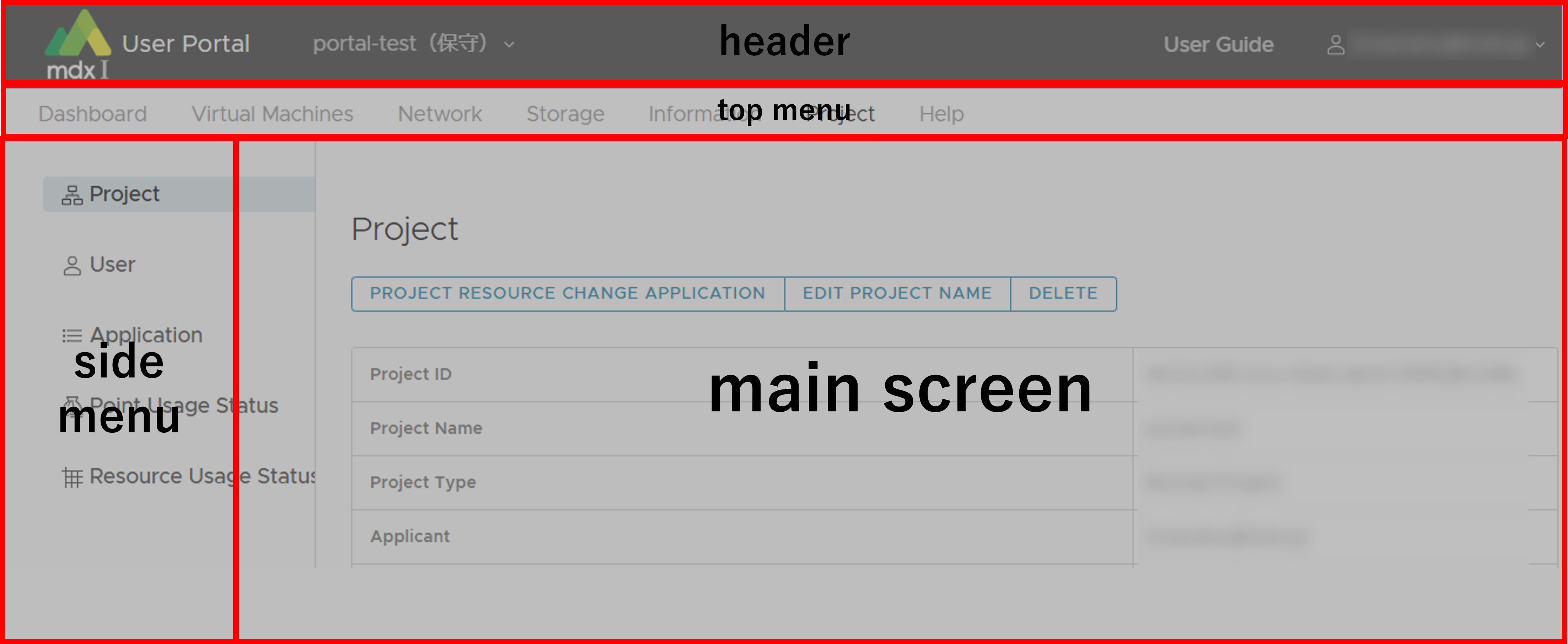
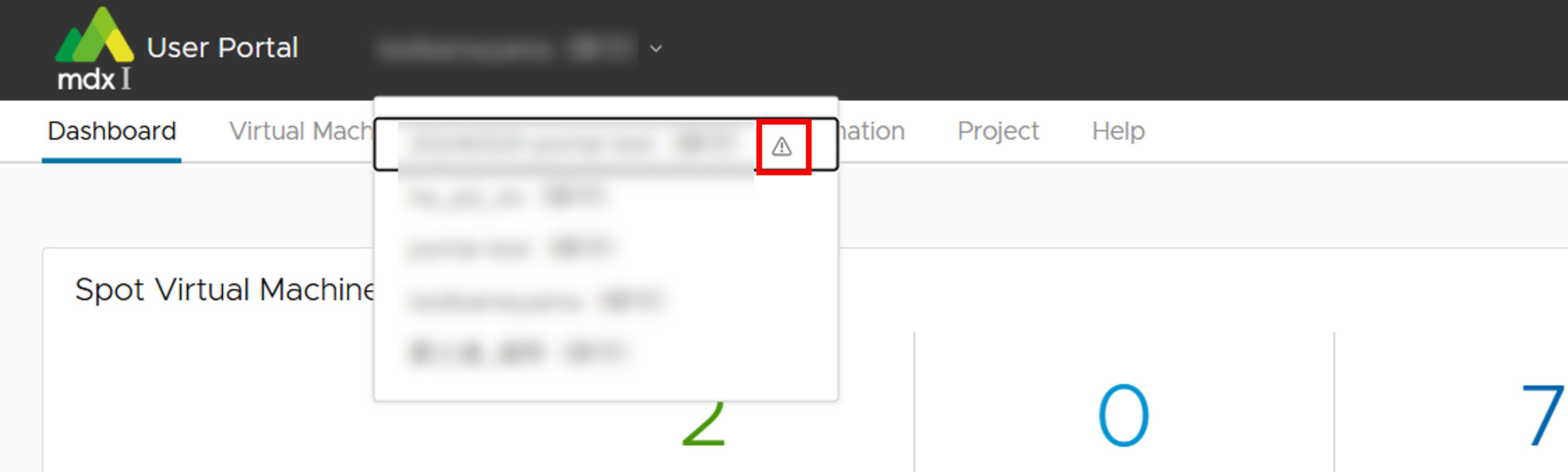
On the project switching screen, projects with a warning mark (A triangle with an exclamation mark) displayed to the right of the [Project name (Institution name)] are suspended or have expired.
1.3.2. Portal timeout period
The Project Application Portal and User Portal will disconnect the login session if there is no activity for more than 3 hours. Please log in again.
1.4. About resource units in mdx
1.4.1. Data unit
1.4.2. About CPU Pack and GPU Pack
The amount of resources available in 1 CPU Pack and 1 GPU Pack are as follows.
Name |
Number of virtual CPUs |
Amount of virtual memory |
Number of GPUs |
|---|---|---|---|
CPU Pack |
1 |
1548MB (Approx. 1.51GB) |
0 |
GPU Pack |
18 |
Approx. 57.60 GB |
1 |
1.5. Basic information on mdx points
1.5.1. About mdx points
1.5.2. Consumption of points
Computing resources allocation for Reserved Virtual Machines and storage resources (Flat-rate)
Calculate consumption points for the amount of resources allocated to the project
- Calculated using the maximum amount of resources allocated within a unit time for each resource type at the point consumption timing.Note that changes in the resources are caused by project resource change application , etc.
- Example: Assuming that the consumption points are calculated at 24:00.If the allocated virtual disk storage resources fluctuate from 100GB to 200GB at 16:00,the consumption points at 24:00 will be calculated based on the allocated resources of 200GB.
Computing resource usage for Reserved/Spot Virtual Machines (Metered rate)
Calculate the consumption points based on the resource usage and uptime of the running virtual machines.
Points are calculated and consumed according to the time spent, even if the work time is less than unit time.
Project examples
Allocated
CPU Pack: 10, GPU Pack 1, Virtual Disk Storage: 100G, High-Speed Storage: 100G, Large-Capacity Storage: 100G
Virtual machine usage results
Virtual machine A: have 2 CPU Pack, used for 10 hours
Virtual machine B: have a GPU Pack, used for 5 hours
Total amount of points consumed per day: 1510 points
Note
Consumption points for resources are determined for each fiscal year, and the following calculations are based on values for fiscal year 2023
Computing resources allocation for Reserved Virtual Machines and storage resources: 1256 points
CPU Pack: 10 packs x 0.2 points x 24 hours = 48 points
GPU Pack: 1 pack x 50 points x 24 hours = 1200 points
Virtual Disk Storage: 100G x 0.03 points = 3 points
High-Speed Storage: 100G x 0.03 points = 3 points
Large-Capacity Storage: 100G x 0.02 points = 2 points
Computing resource usage for Reserved/Spot Virtual Machines: 254 points
CPU Pack: 2 packs x 0.2 points x 10 hours = 4 points
GPU Pack: 1 pack x 50 points x 5 hours = 250 points
2. Usage flow (quick start guide)
2.1. Apply for a project
To start using mdx, it is necessary to enter the purpose of use, period of use, and information on each person in charge, and apply (Project application) .
Project application is made by logging into the Project Application Portal .
For the method of logging in to the Project Application Portal please confirm here .
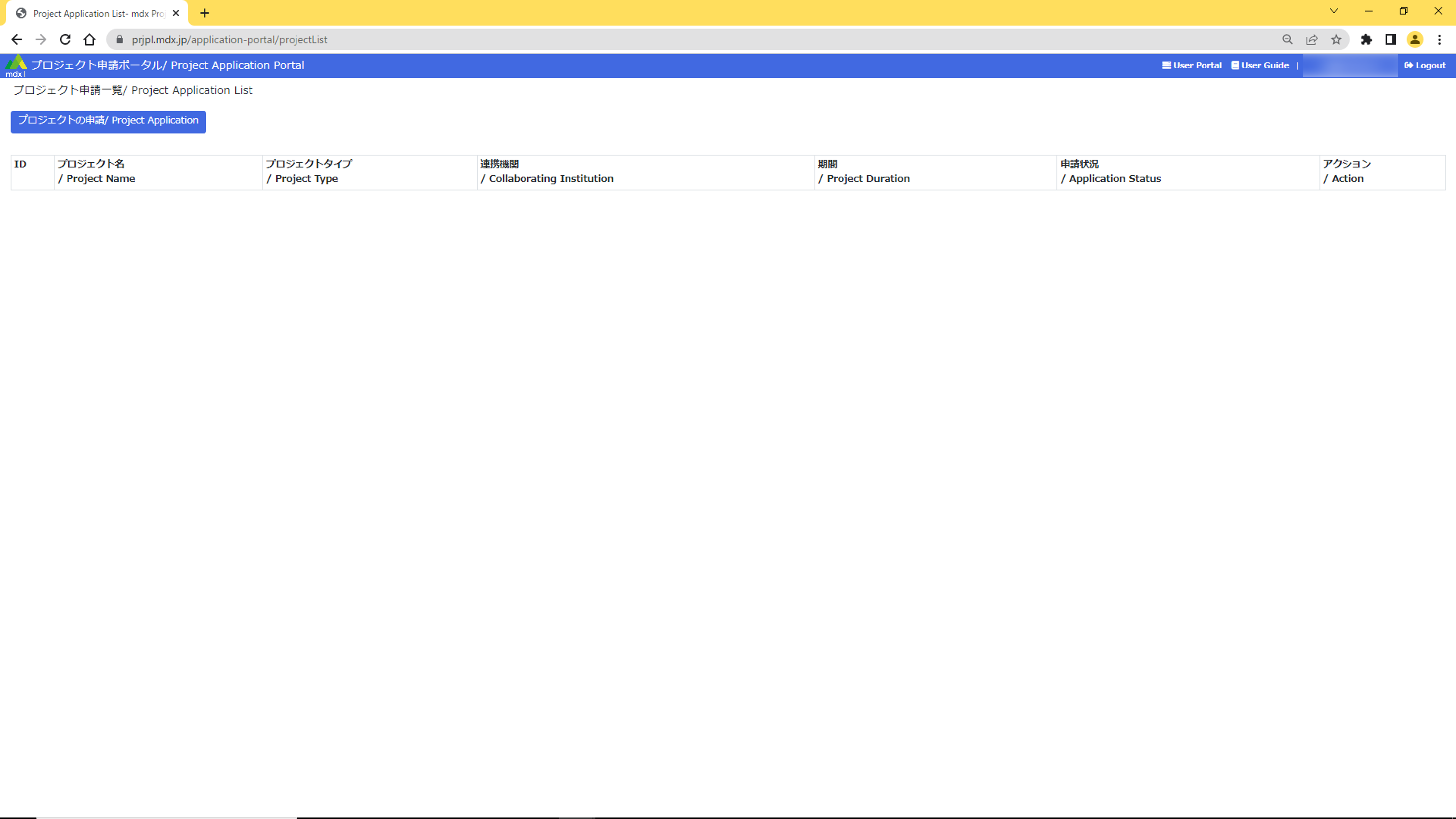
Please move to the application screen from [プロジェクトの申請/ Project Application], fill in the required information, and apply.
Wait for approval by the institutional administrator of the applied institution.
Application status can be confirmed in the Project Application Portal.
For details on the procedure, please confirm with here .
2.2. Apply to purchase points for project use
To use mdx resources, you need to apply for point purchase on the the Project Application Portal . The purchase application will be available after the project is approved.
Please check the Payment method and Payment Budget for payment methods of purchase points.
Click [ポイントを購入する/ Buy Points] and then click [購入する/ Purchase] next to project where you want to use the resources. After that, fill in the required information on the application screen and submit your application.
Wait for the mdx administrator to approve.
Application status can be confirmed in the Project Application Portal.
For details on the procedure, please confirm with here .
2.3. Apply for resources to be used in the project
Apply for mdx resources to be used in the project.
Resource application is made by logging in to the User portal .
Please confirm here for method of logging in to the user portal.
Please fill in the required resources and submit the application from [PROJECT RESOURCE CHANGE APPLICATION].
Wait for approval by the institutional administrator of the applied institution.
Application state can be confirmed on the user portal.
For details on the procedure, please confirm with here .
2.4. Create/Start the virtual machine
All virtual machine operation is performed through the user portal.
Virtual machine can be created from a virtual machine template or an iso image. By using a virtual machine template, common system settings can be omitted.
If virtual machine template is used, the public key is required to access the virtual machine remotely. Please prepare your own.
After creating the virtual machine, start the created virtual machine.
Virtual machine status and other information can be confirmed in the user portal.
For details on the procedure, please confirm with here .
2.5. Network settings
By default, the created virtual machine is not accessible from the outside. All communication from the outside (Internet) is blocked for security reasons.
Set DNAT and ACLs in the User portal .
Network settings are the responsibility of the user.
If settings are mistaken, the virtual machine may become the target of an attack, resulting in a serious security incident. Please be cautious.
Please refer to the service network item on the “Virtual machine” page of the user portal to confirm the local IP address of the virtual machine, which is necessary information for the configuration.
For details on the procedure, please confirm here .
2.6. Using a virtual machine
From your own device, access the configured global IP address using the registered key pair’s private key and use the virtual machine.
3. About how to login to the portal
This page explains how to login using GakuNin and mdx local accounts at each portal.
3.1. How to login using your GakuNin account
- From the pull-down menu (Down arrow icon) in the [Login with Academic Access Management Federation in Japan (GakuNin)] menu on each portal login pagewith the affiliated institution selected click [選択](Select).
Project Application Portal
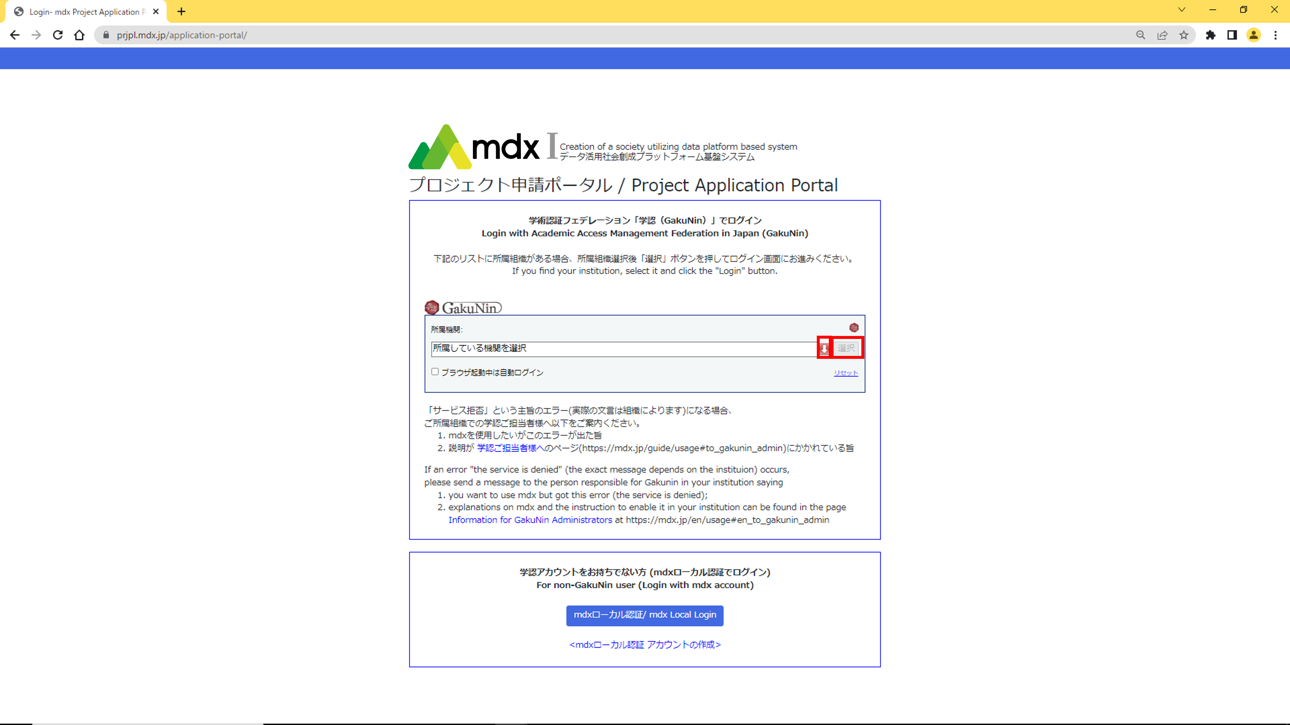
User Portal

The prescribed authentication process prepared for each institution to which you affiliated is performed.
- A screen will appear asking you to confirm your consent to submit user information to this service.After confirming the contents, select an agreement method and click [同意](Agree).

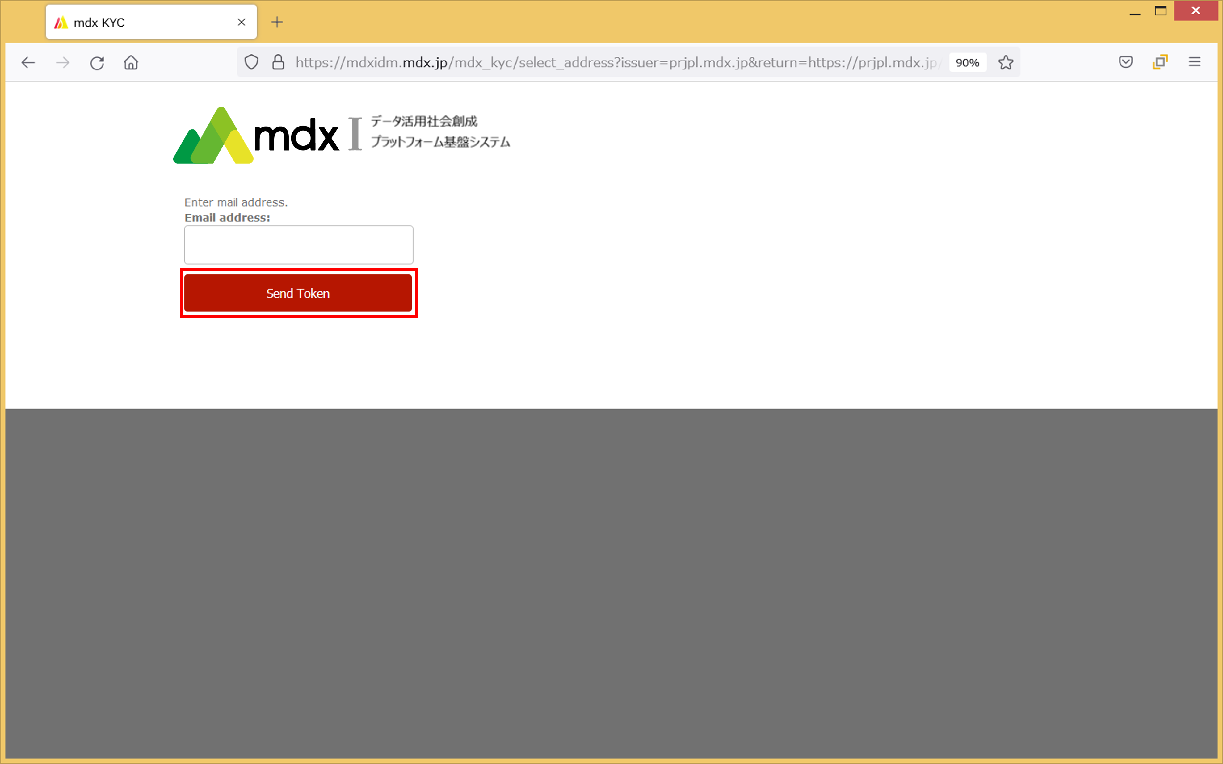
We will confirm your identity by e-mail. Enter an email address that ends with either “*.ac.jp”, ” *.go.jp” and an email address that you can receive and click [Send Token].
The results of the email verification will be retained for 30 days after the verification is conducted. After 30 days, the applicant will need to be confirmed again.
Depending on the institution, this screen may not be displayed after Step 3, and the portal TOP screen in Step 6 may be displayed. In that case, please skip step 4, 5.
An authentication e-mail will be sent to the e-mail address you entered.
Copy the [Token] string from the email you received, paste it into the [Token] entry field in the portal, and click [Verify Token].
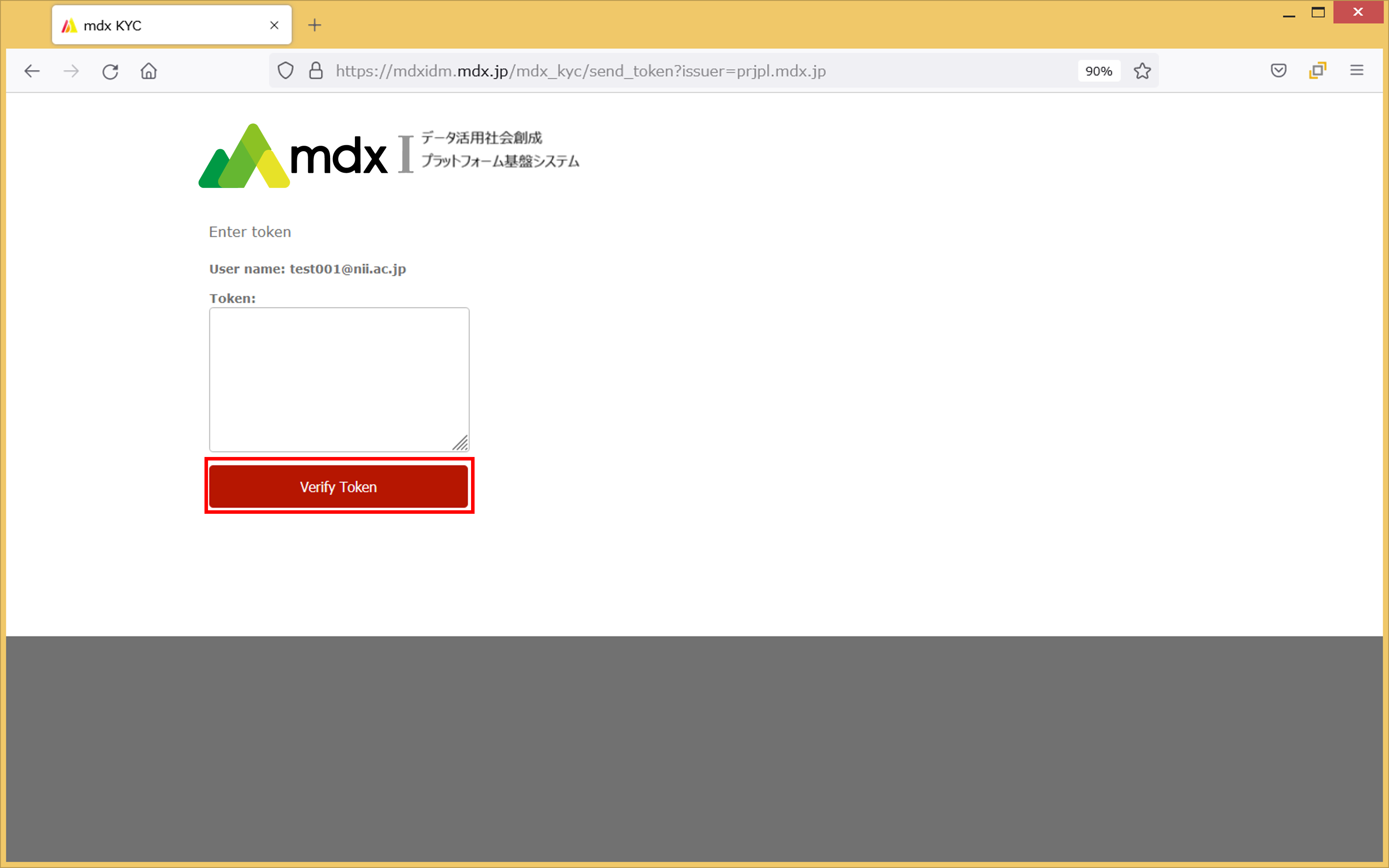
Click on the mentioned URL in the email you received.
Once the authentication is completed and the TOP screen of the portal shown below is displayed, the login will complete.
Project Application Portal
User Portal
3.2. How to login using mdx local account
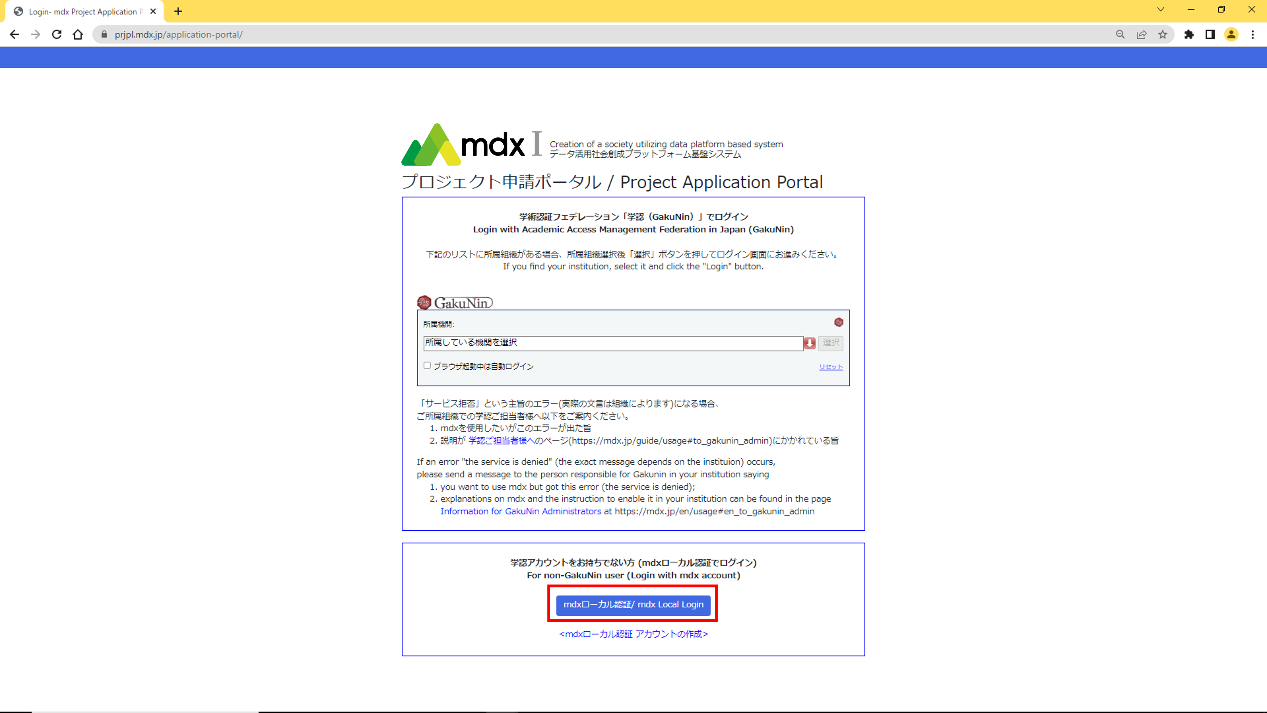
Click the Login button for mdx authentication in the [For non-GakuNin user (Login with mdx account)] menu on each portal login page.
From the Project Application Portal: [mdxローカル認証/ mdx Local Login]
From the User Portal: [MDX LOCAL LOGIN]

Enter the username and password for your mdx local account and click [Login].
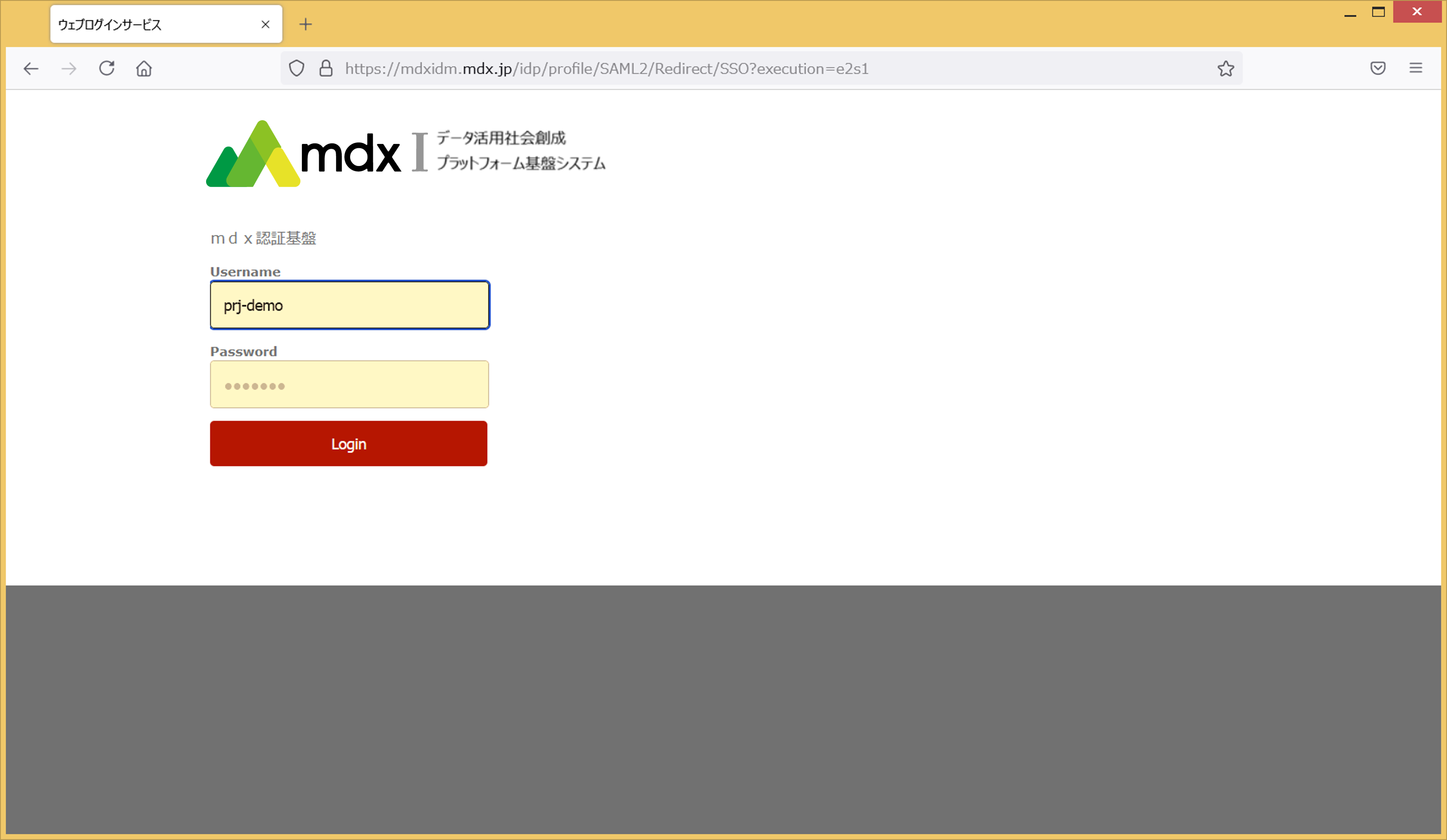
Authentication is then performed using a two-factor authentication service.
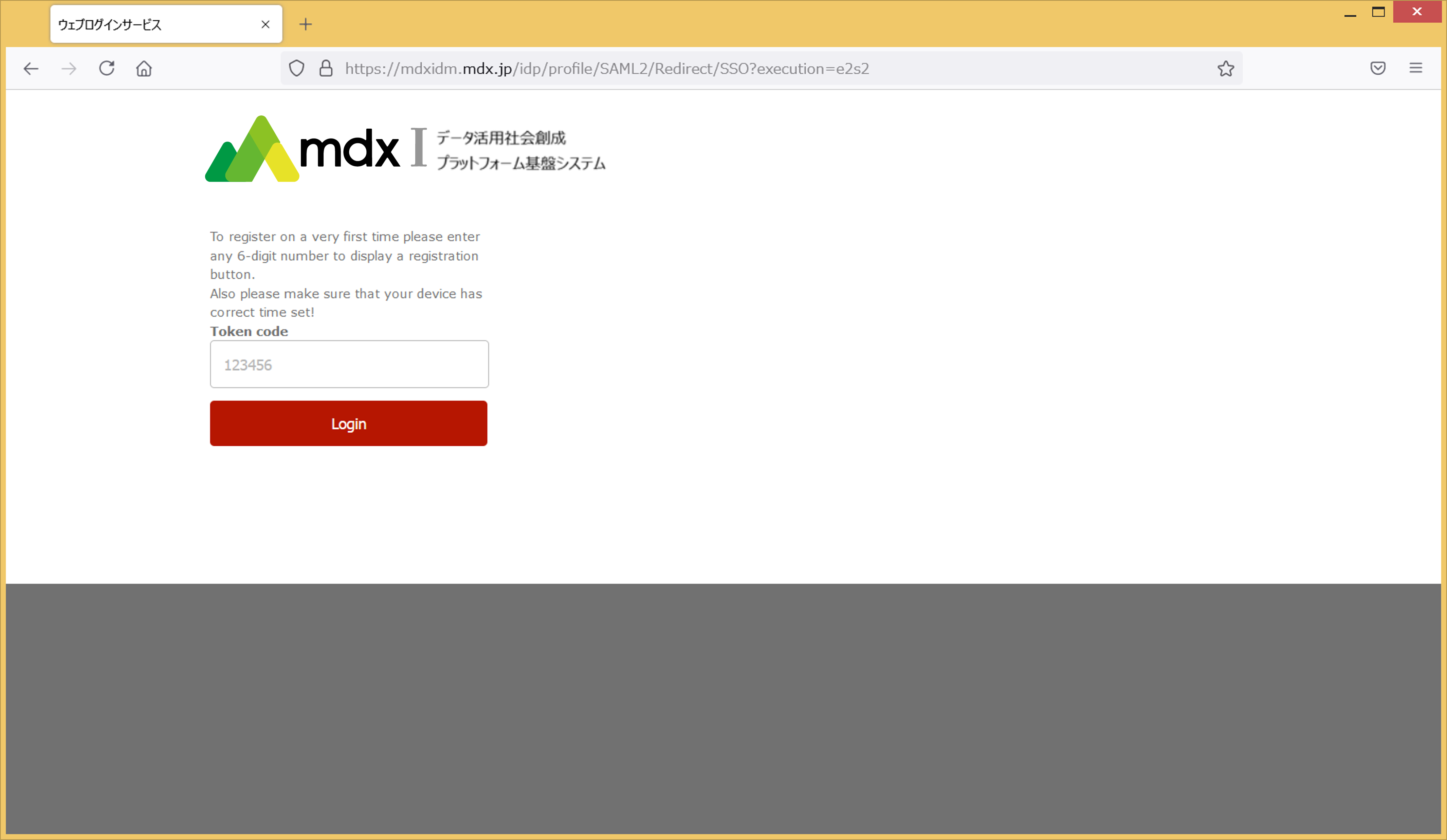
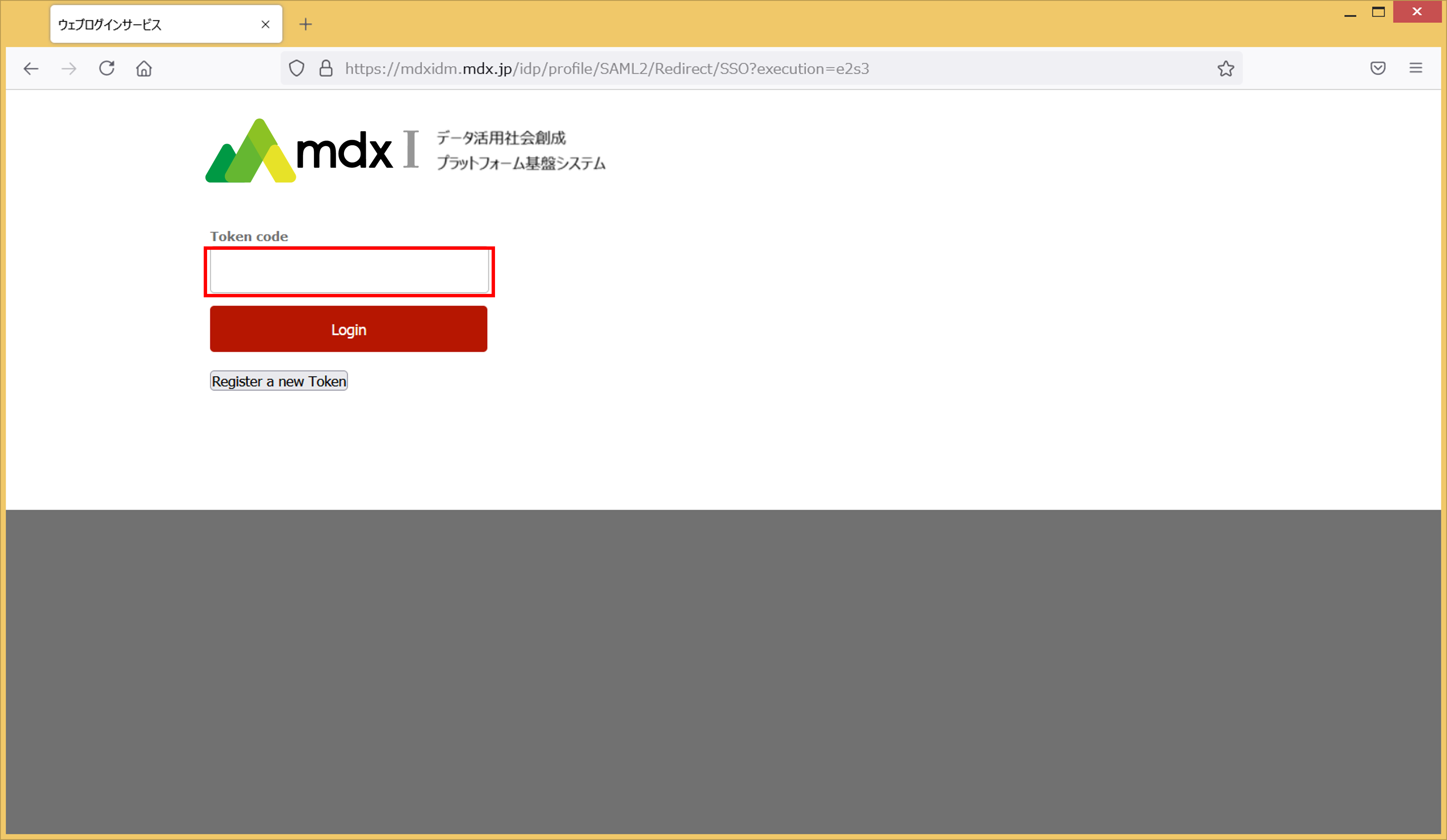
If you are authenticating for the first time, enter an arbitrary 6-digit number in the [Token code] field and click “Login” to proceed to the next step.
If you are authenticating for the second or subsequent time, enter the 6-digit number displayed in your mdx account on the two-factor authentication service in the [Token code] field, click [Login], and proceed to step 8.
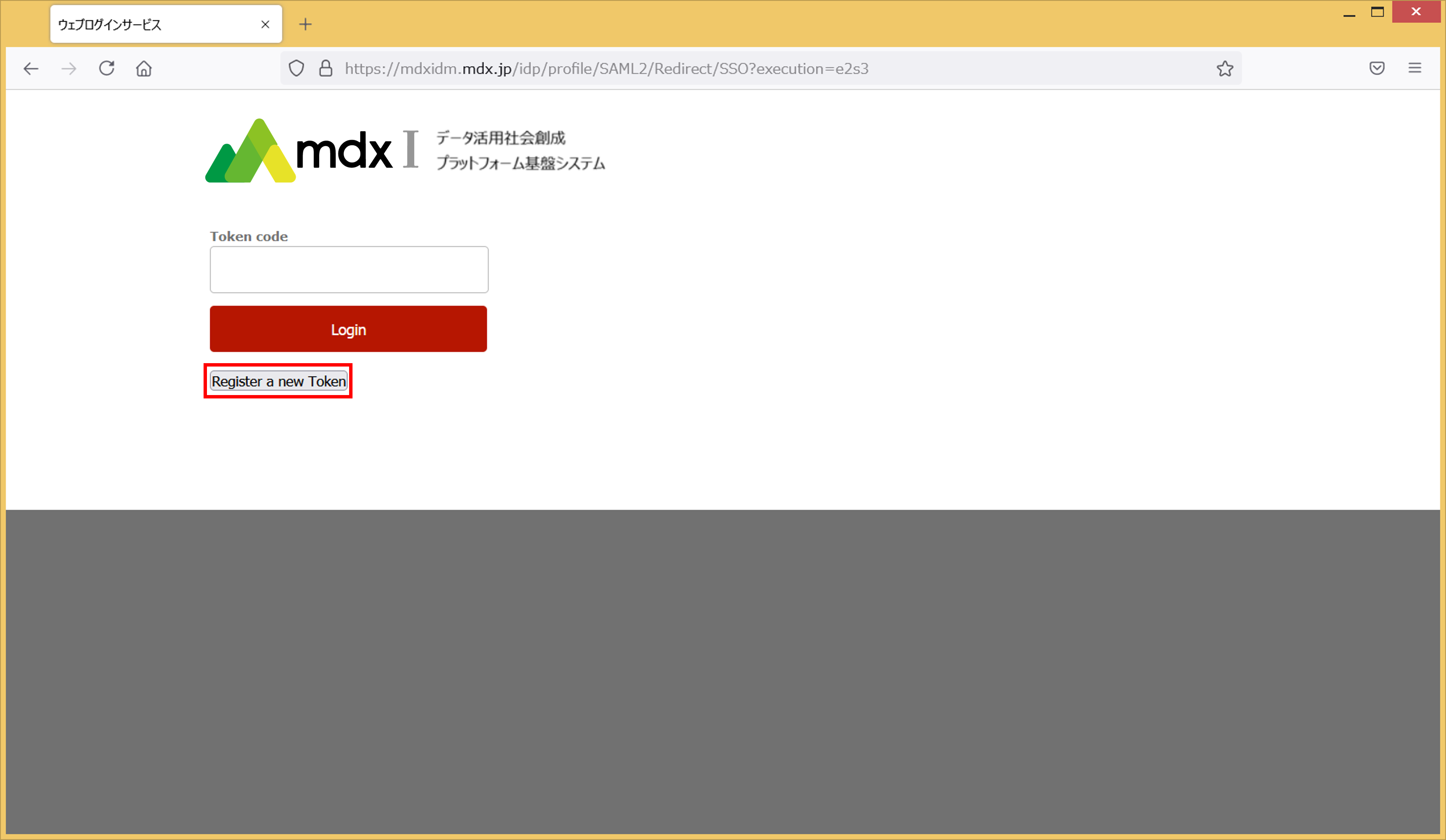
Click on [Register a new Token].
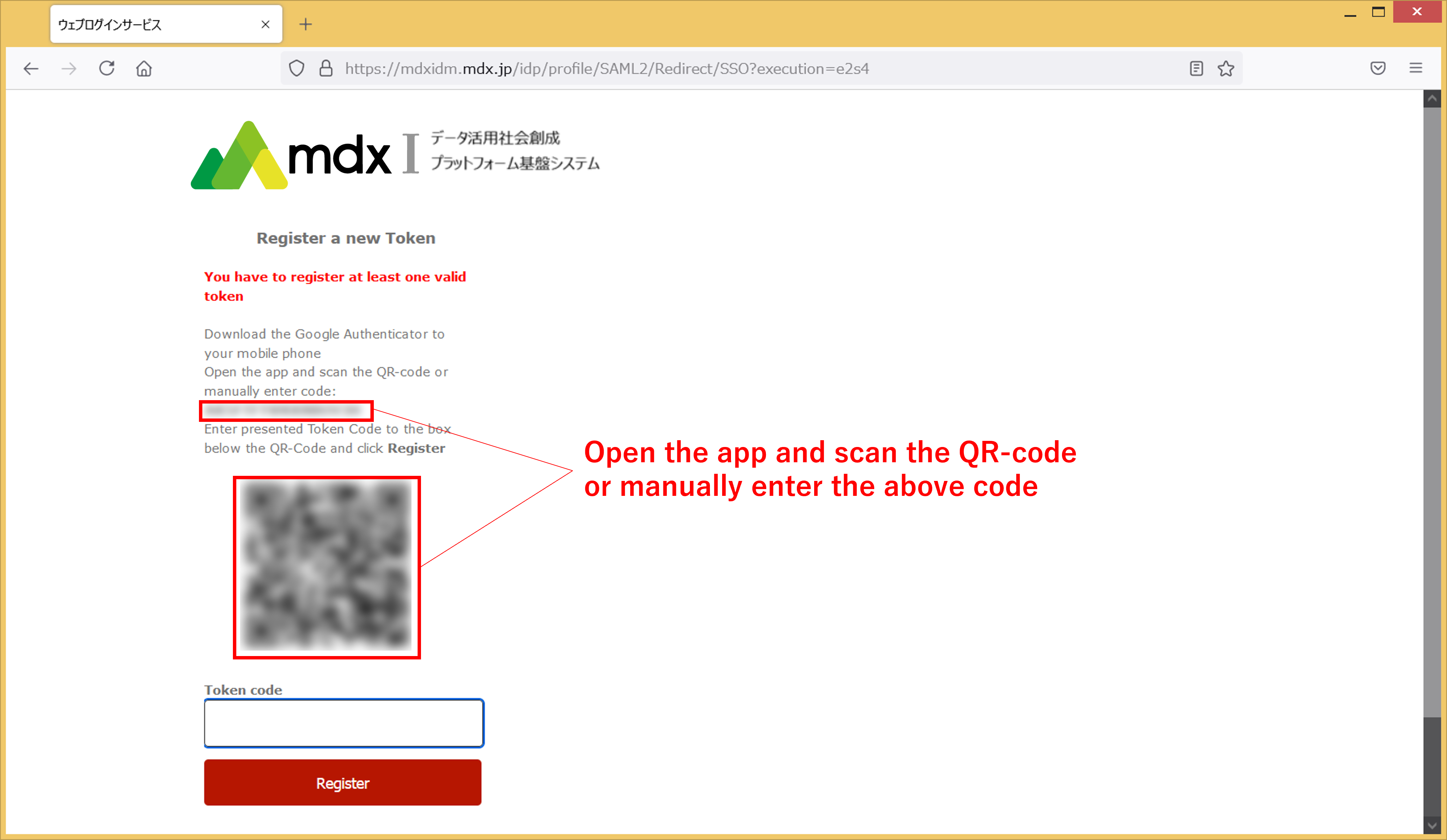
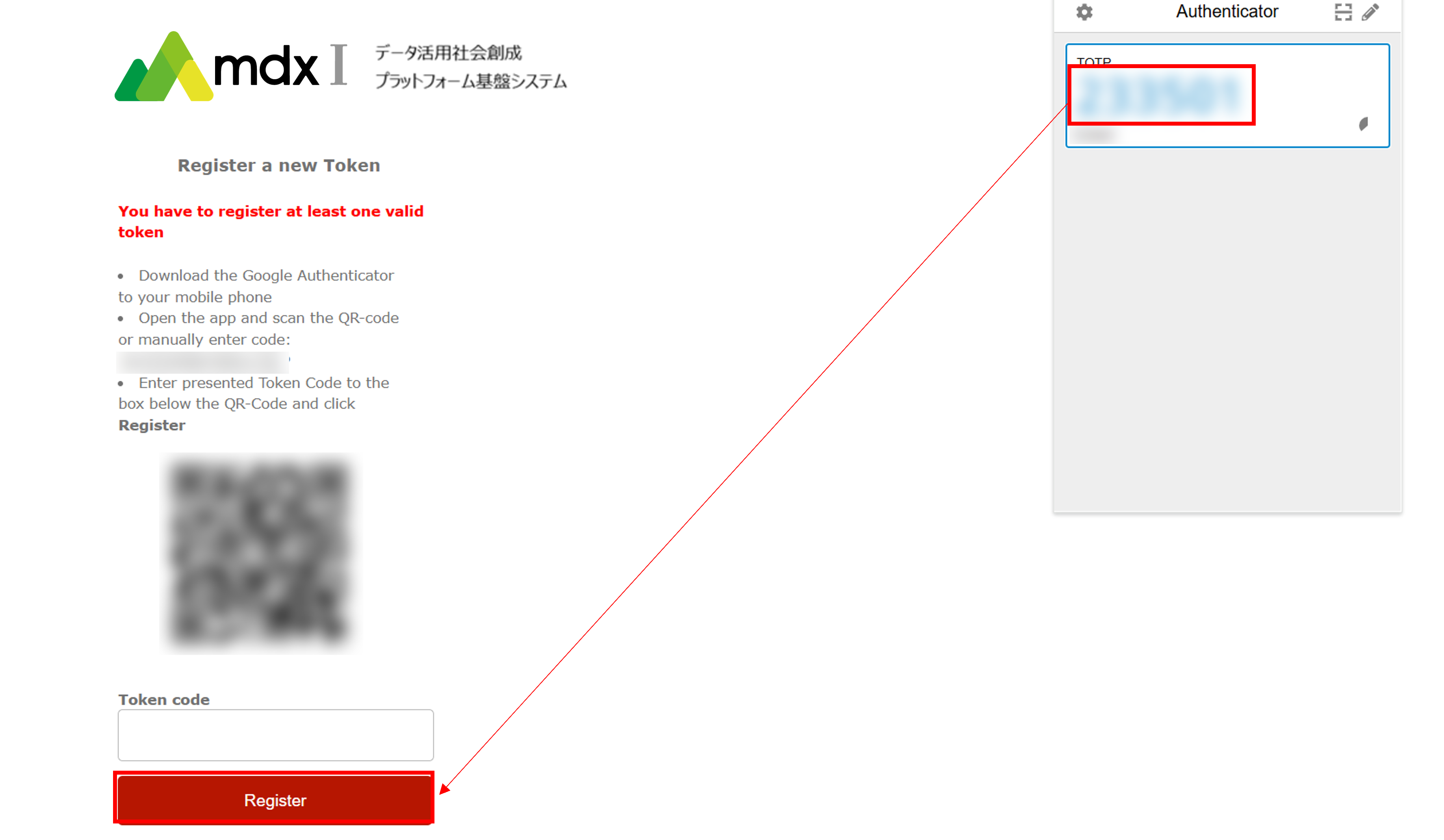
- Scan the displayed QR code into the two-factor authentication service or enter the 16-digit code displayed in the [manually enter code] section into the two-factor authentication service.Your mdx account will be registered in the two-factor authentication service and a 6-digit number associated with it will be displayed. Enter this number in [Token code] and click [Register].
The screen to enter the token will be displayed again, so enter the 6-digit number generated by the two-factor authentication service into [Token code] and click [Login].
A screen will appear asking you to confirm your consent to send user information to mdx’s service. After confirming the contents, select the method of consent and click [同意](Agree).
Authentication is complete when the TOP page of the portal is displayed.
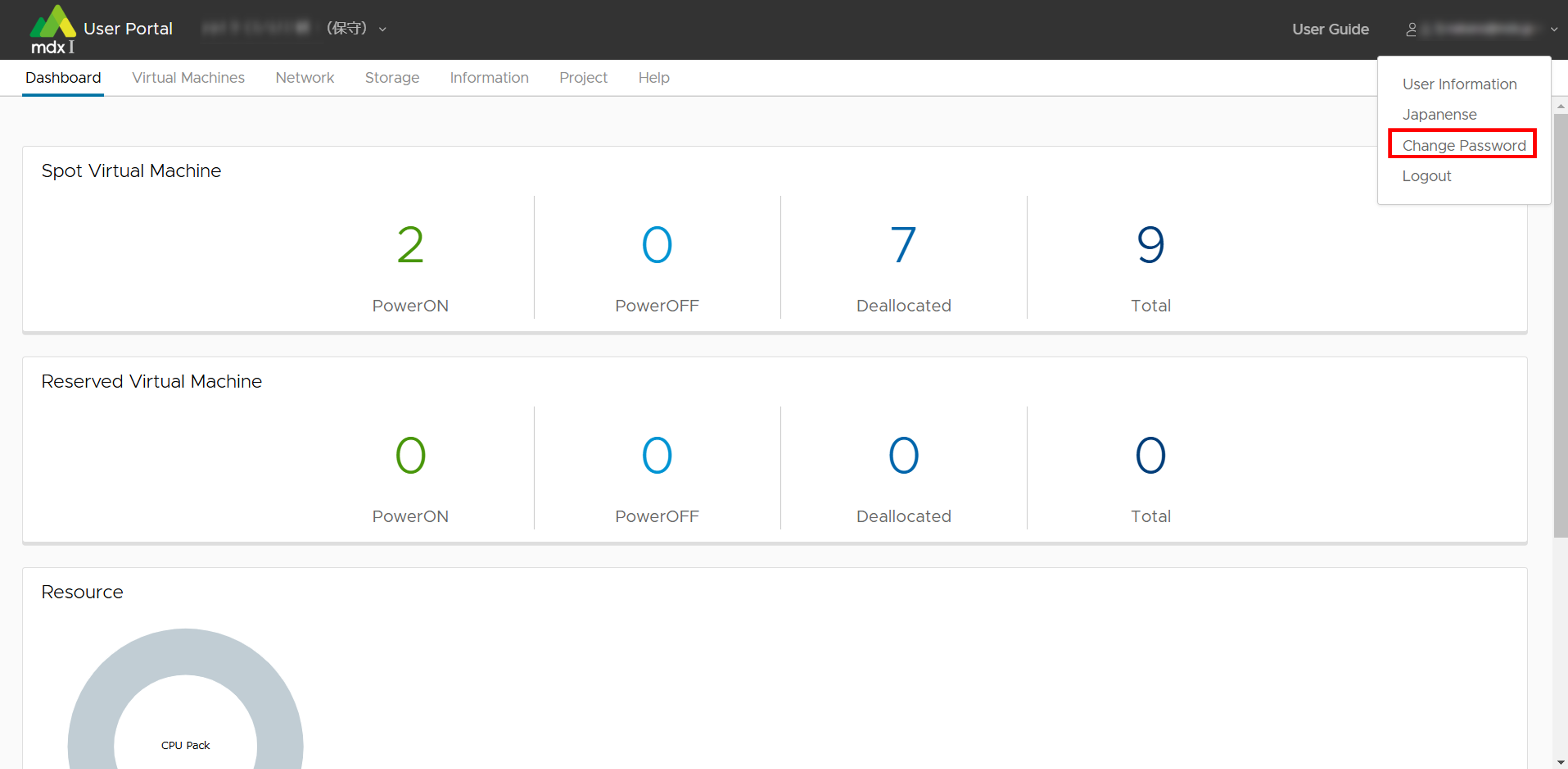
3.2.1. How to change password for mdx local account
If you are using an mdx local account, you can change your login password from the User Portal.
Click on the username in the upper right header section of the screen.
Click [Change Password] from the choices displayed.
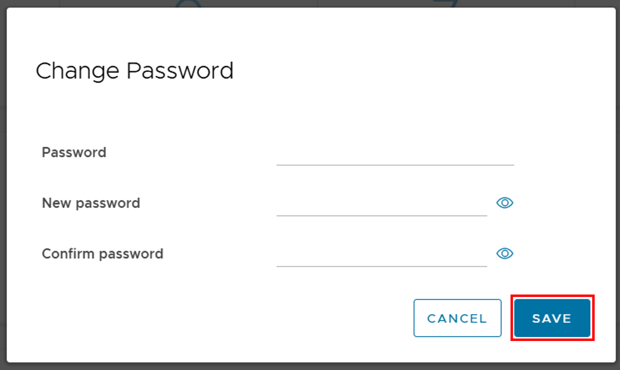
Enter your current and new passwords.
Once entered, click [SAVE] to complete the password change.
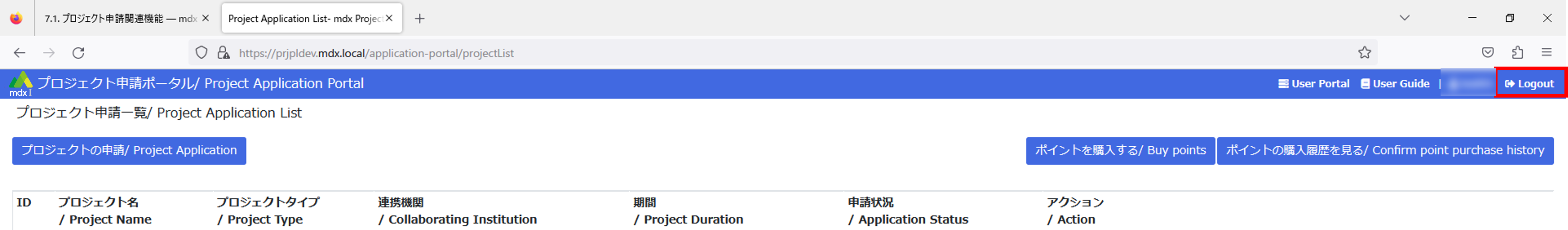
3.3. How to log out of the portal
To log out of each portal, please follow the instructions below.
Project Application Portal: Click the logout button in the upper right corner of the screen.
User Portal:
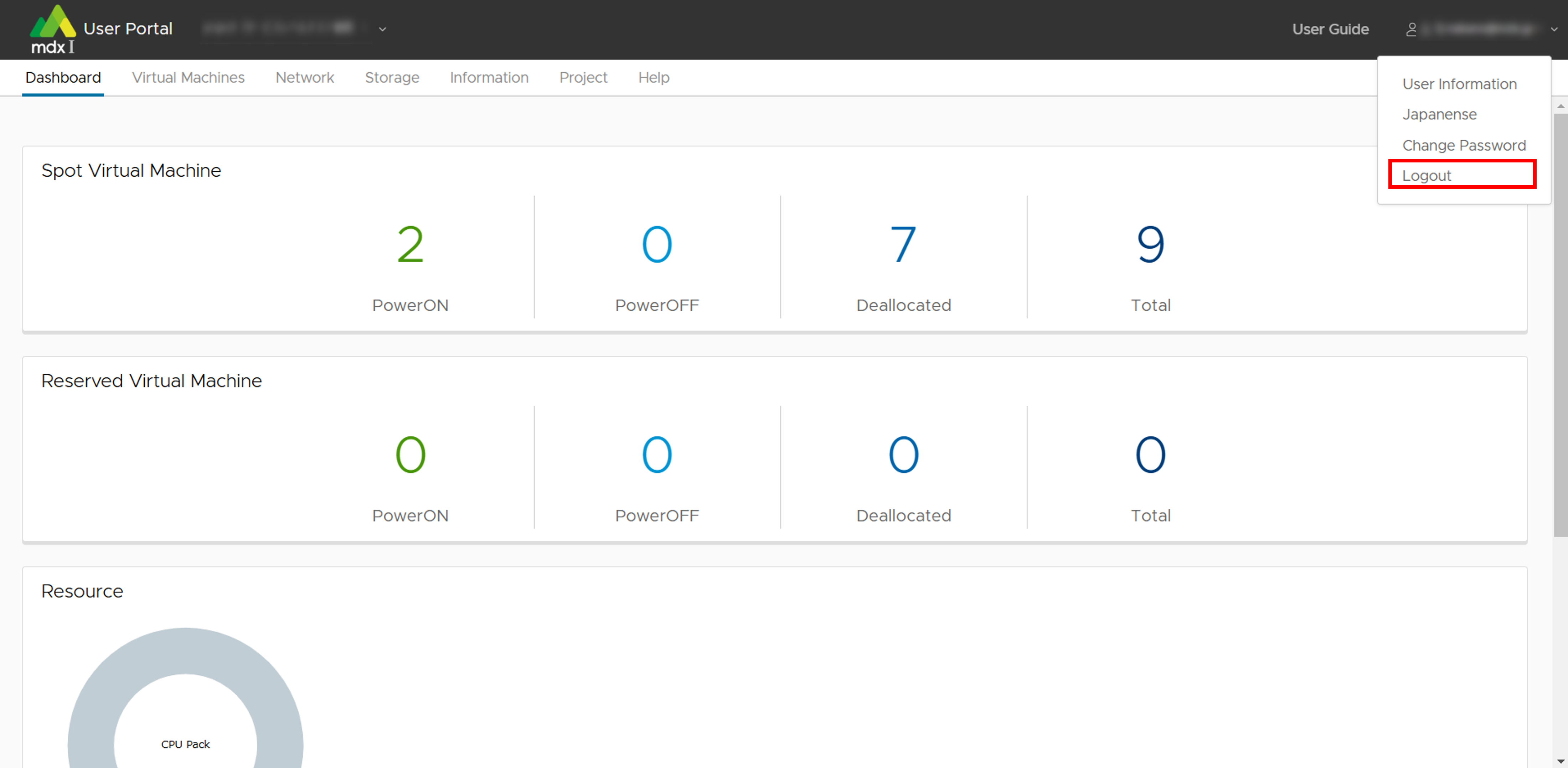
Click on the username in the upper right header section of the screen.
Click [Logout] from the choices displayed.
3.4. About two-factor authentication
3.4.1. For smartphones
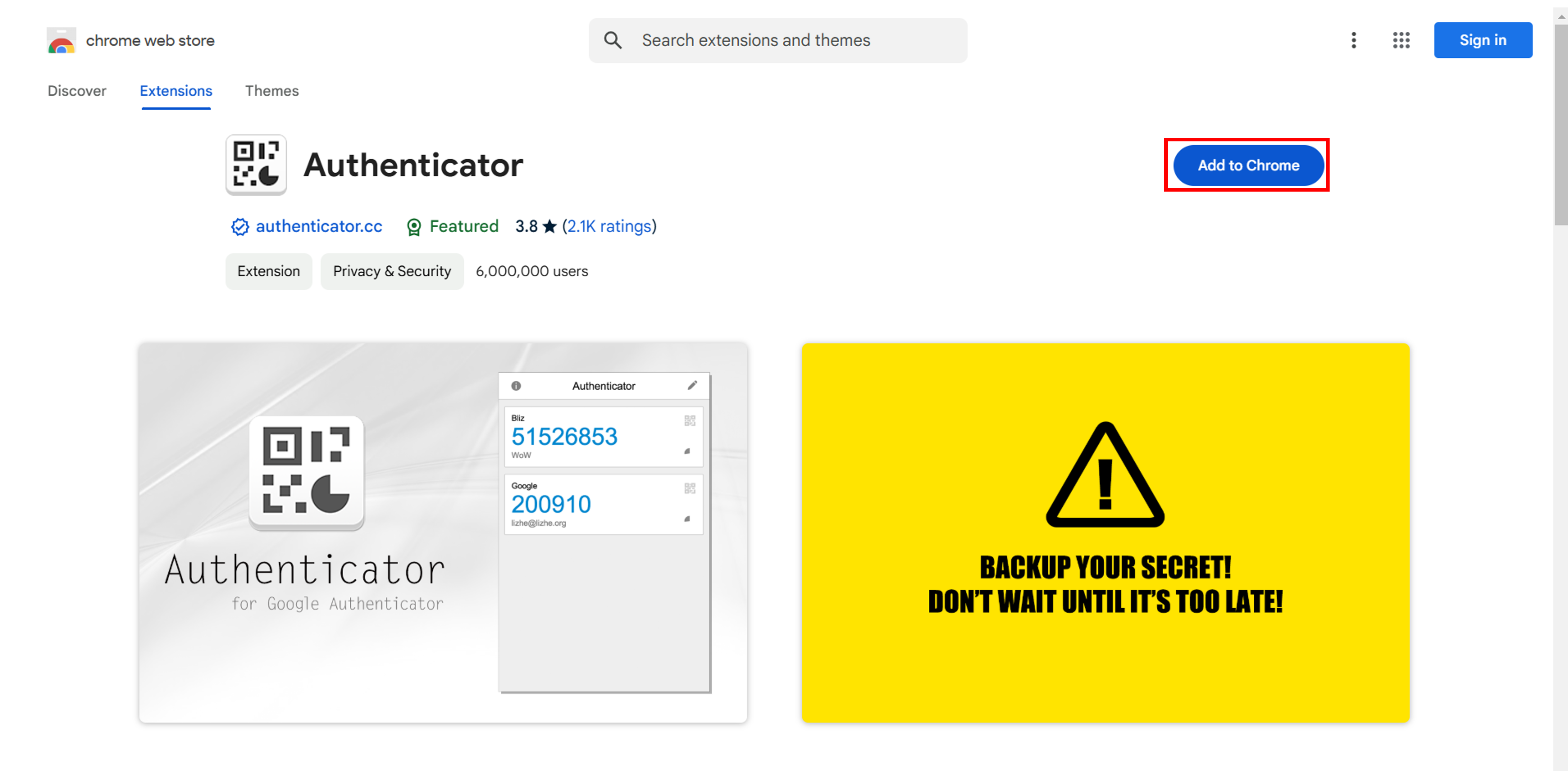
3.4.2. For PC
From Google Chrome browser access this URL .
Click [Add to Chrome].
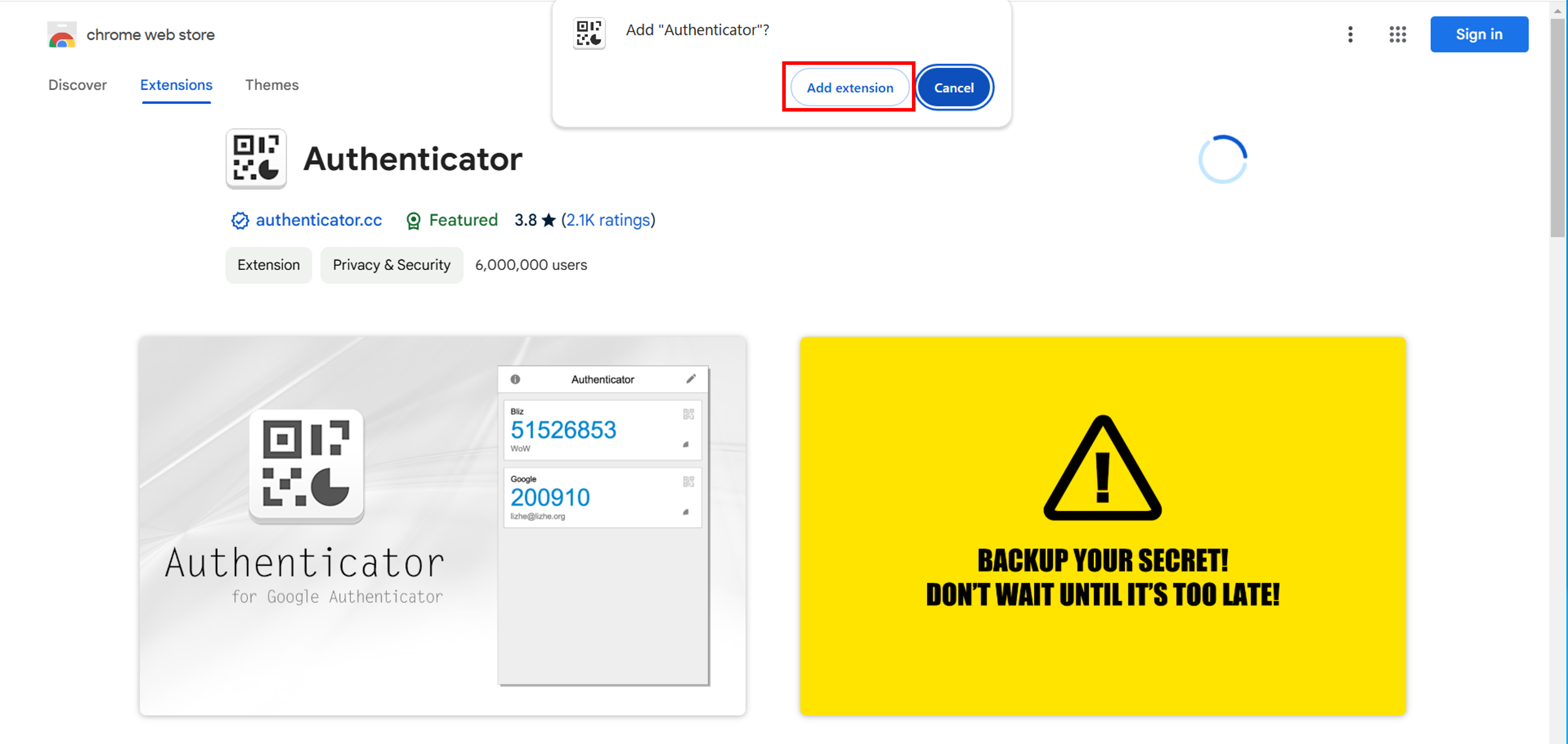
When the pop-up window appears, click [Add extension] to finish adding the plug-in.
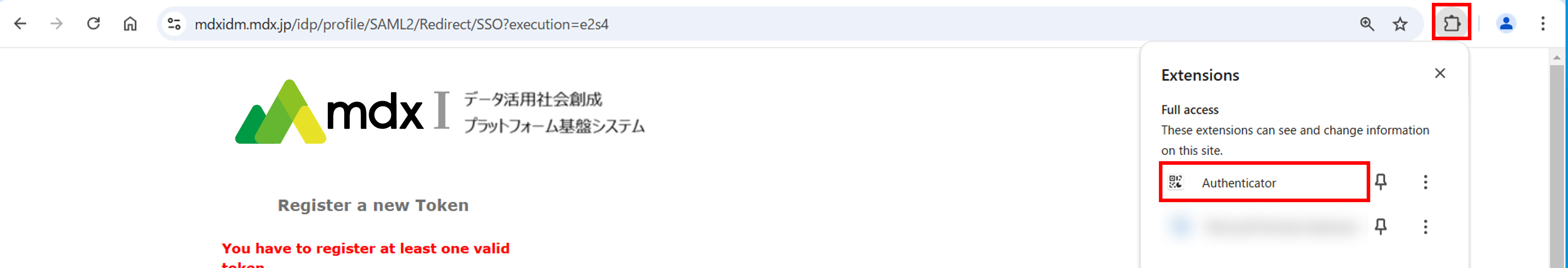
- To use two-factor authentication, go to the screen where the QR code for two-factor authentication is displayed.Click on the extended functions button (The button that looks like a puzzle piece) from the Google chrome browser menu bar.
Click [Authenticator] from the displayed plug-ins. If a pop-up window appears asking for permission to use the plugin, click [Allow].
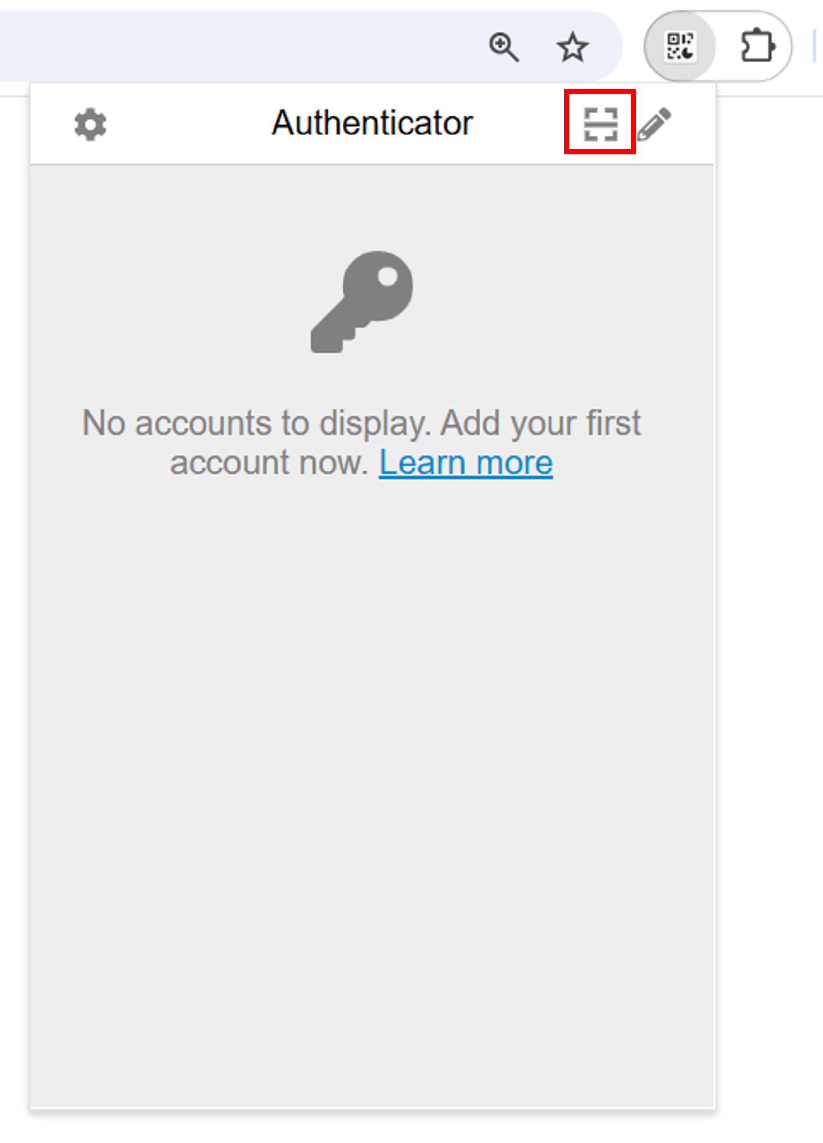
The authentication plug-in window will appear. Click the scan button in the upper right corner.
- The screen will turn white and a tutorial on how to scan will be displayed.Follow the instructions on the display and drag the mouse cursor around the QR code displayed on the page you wish to authenticate this time.

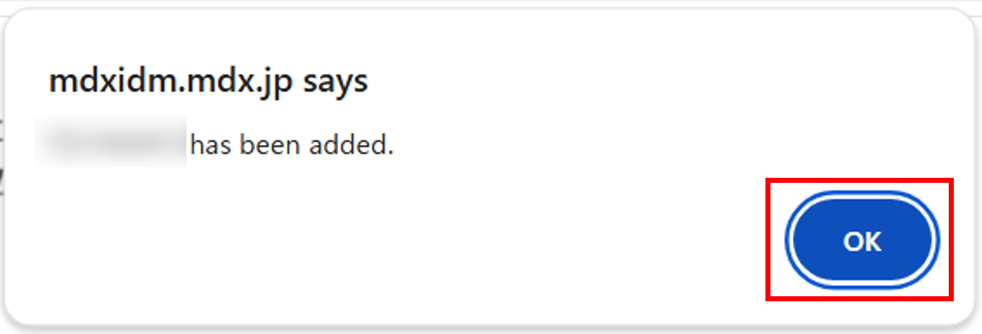
Once the QR code is confirmed, a pop-up will notify you at the top of the screen that your account has been added. This completes the account addition process.
- When you reserved the authentication plugin from the menu bar plugins again, the added account name and one-time password will be displayed.Enter the displayed one-time password in the input field on the page where authentication is performed to proceed with the authentication process.
4. Project application process
4.1. Apply for the project
Log in to the Project Application Portal.
Click on [プロジェクトの申請/ Project Application] in the top left-hand corner of the screen.
Enter the required items for the project application.
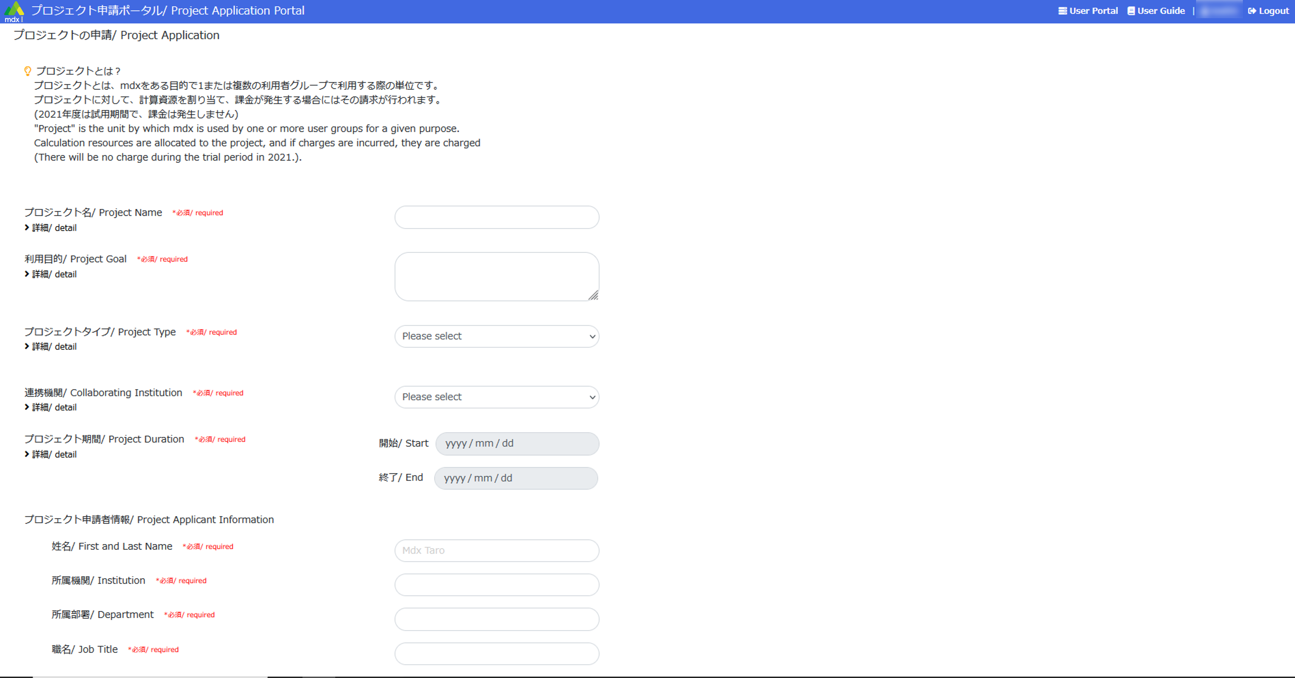
All items marked [必須/ required] are mandatory and must be filled in.
Click on [詳細/ detail] to see a detailed description of each item.
Please refer to Details of project application for the contents of the input items.
Once it is finished entering, click [申請/ Apply] at the bottom of the application screen.
- If the information entered is incomplete, an error message will be displayed above the application button.Also, the name of the incomplete item will be displayed in red, please correct it and click [申請/ Apply] again.
- When returned to the project application list screen, the status of the project that have been applied for is displayed as [申請中/ applied].This completes the project application process.
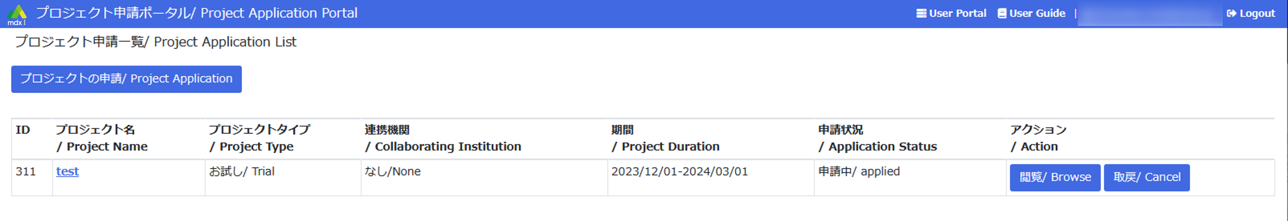
When the project is approved, it can be logged in to the user portal as a user of that project. You can also apply for a project in the following ways.
4.1.1. Withdraw the project application/re-apply it after making necessary corrections.
After withdrawing the project using the Cancel function , it can be re-applied by using the Modify function .
4.1.2. Apply by reusing past project applications
The project’s Copy function can be used to apply by reusing and partially modifying the application contents of rejected or approved projects.
Please confirm here for details on other project application-related functions.
4.2. Add a user to the project
Add users to operate the project together after approval. The work is done on the user portal.
Log in to the user portal.
Click on [Project] from the top menu.
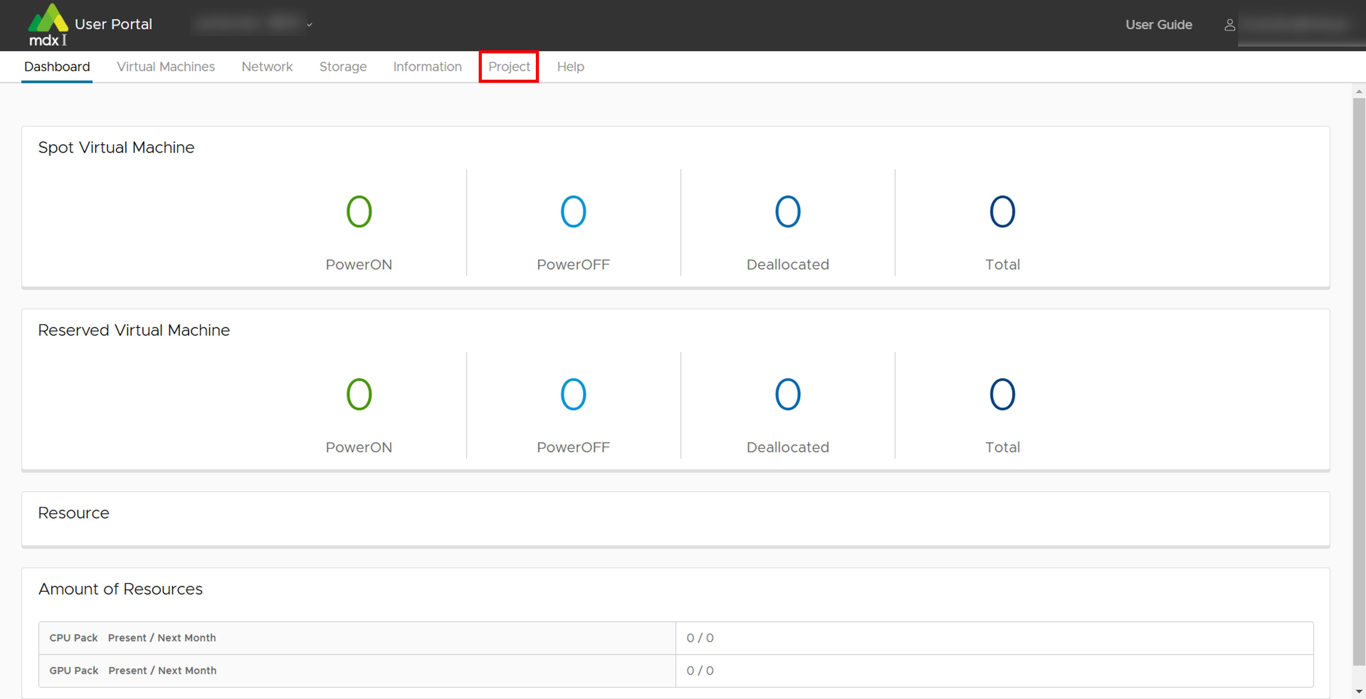
Click on [User] from the side menu.
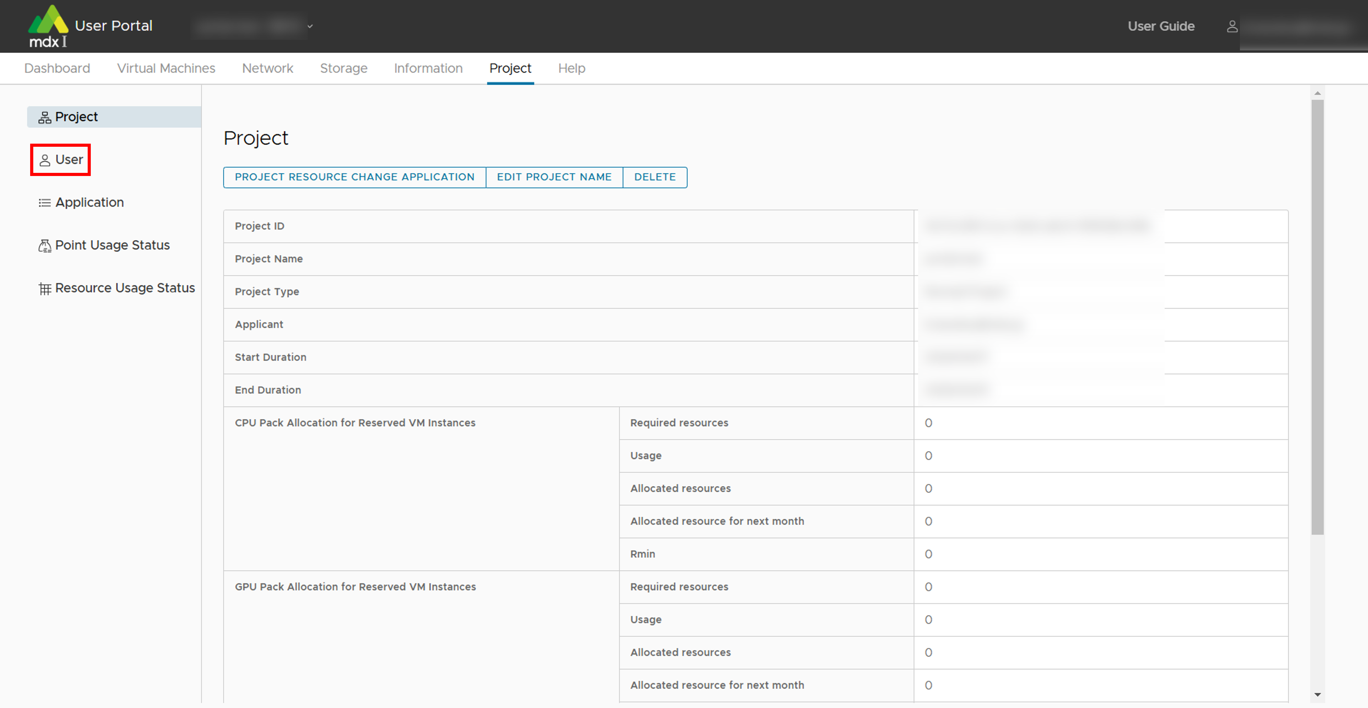
Click on [+PROJECT USER] at the top of the list in the main screen.
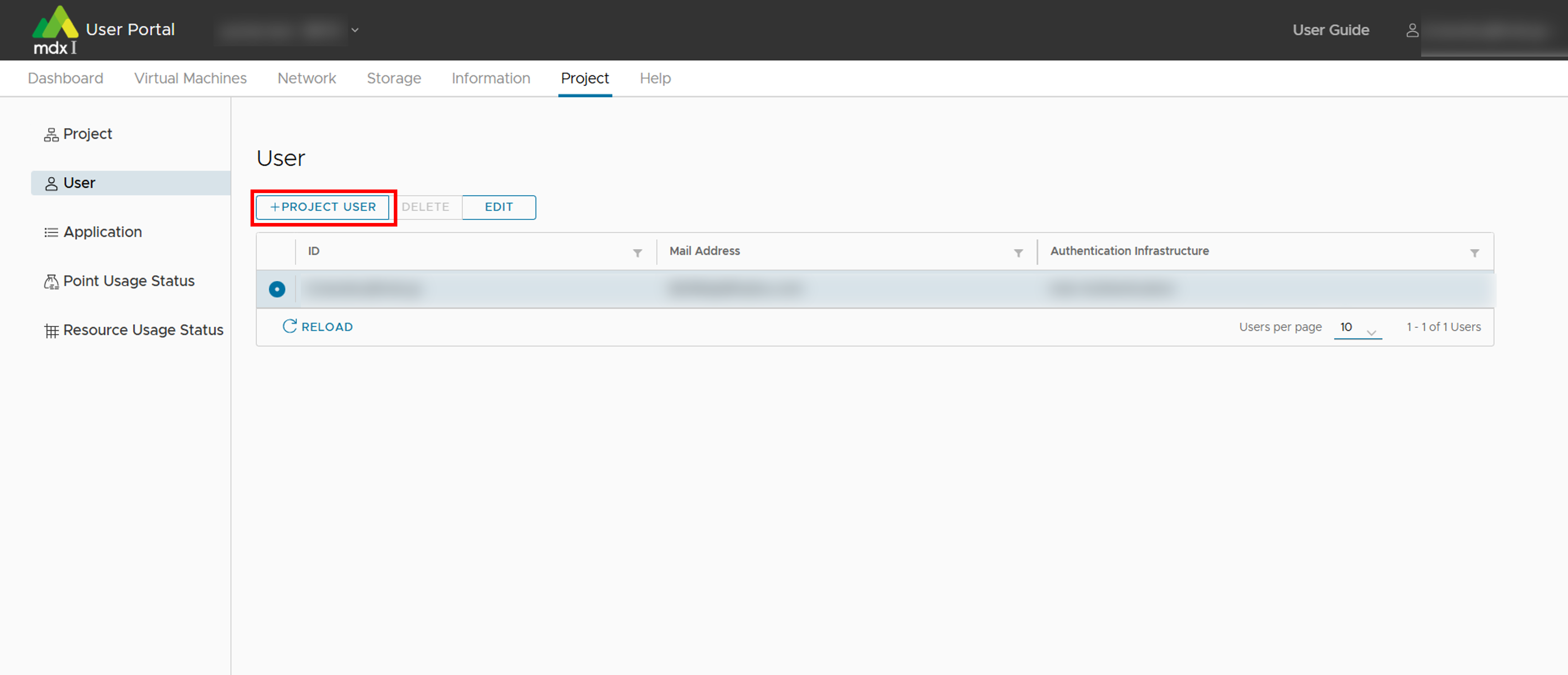
Enter the required information and click [ADD] when completed.
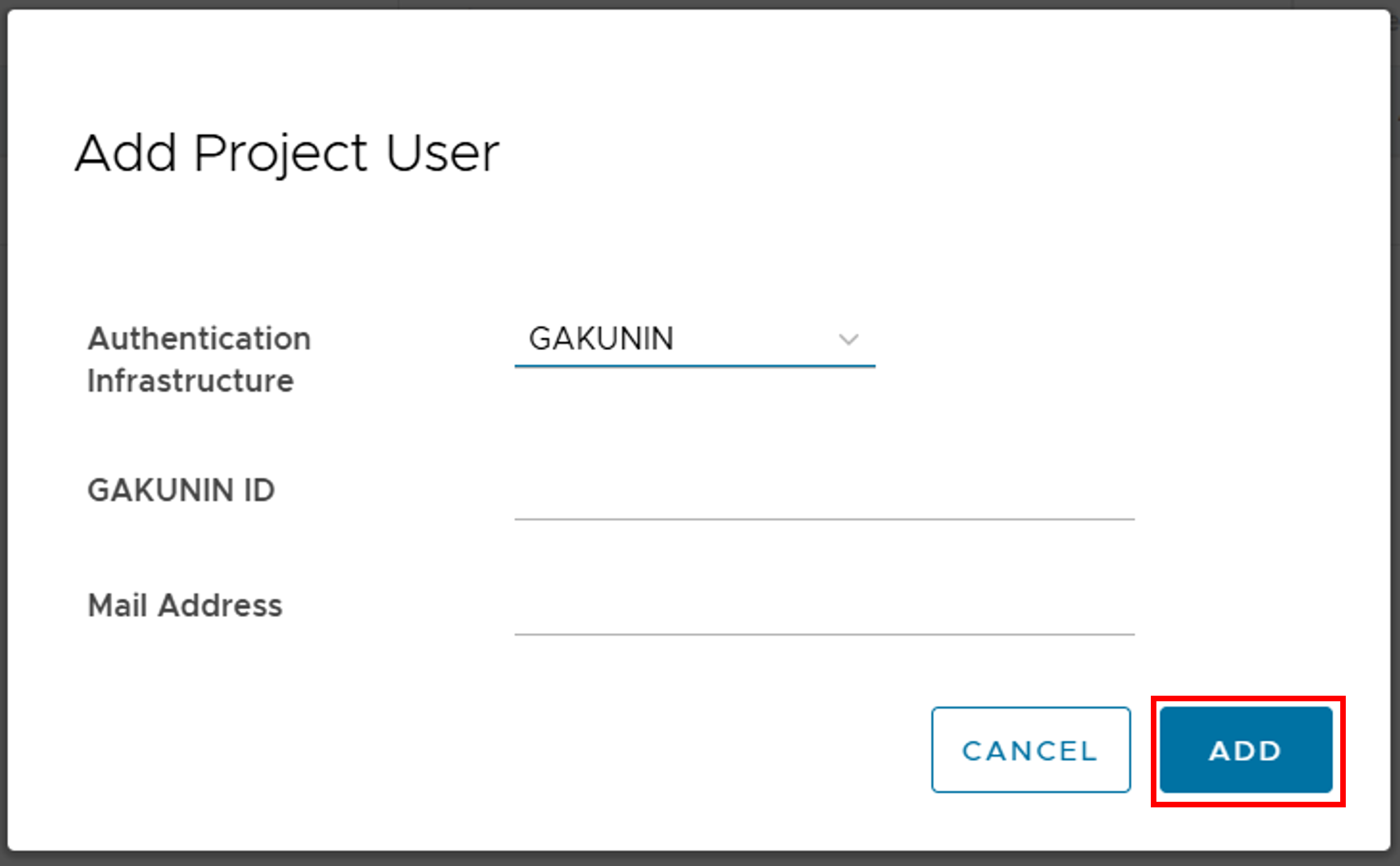
Authentication: Specify the account used by the user, either GakuNin or mdx account (mdx authentication).
- Enter the GakuNin ID or mdx unique ID: Please enter the ID of the user need to be add. (In mdx, the eduPersonPrincipalName provided by each IdP is used as the ID).The ID of the user to be added needs to be checked by the user themselves.Please inform the user being added to log in to the application portal and confirm the ID, displayed in the top right corner of the screen.If the user being added is using an mdx account (mdx authentication), please enter the string before @ in @mdx.jp.
Email address: User’s contact email address
Note: If using an mdx account, an account with the same ID must already be registered in the mdx system by an mdx administrator.
5. Flow of point purchase application
5.1. Application to purchase points
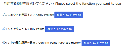
Move to the screen list of the projects for which you want to purchase points by doing any of the following.
Click [移動する/ Move to] to the right of “ポイントを購入する / Buy Points” on the screen to select the function you want to use.
Click [ポイントを購入する/ Buy Points] on the “プロジェクト申請一覧/ Project Application List” screen.
Click [購入する/ Purchase] in the Action column of the project for which you want to purchase points.
Enter the items required for the point purchase application.
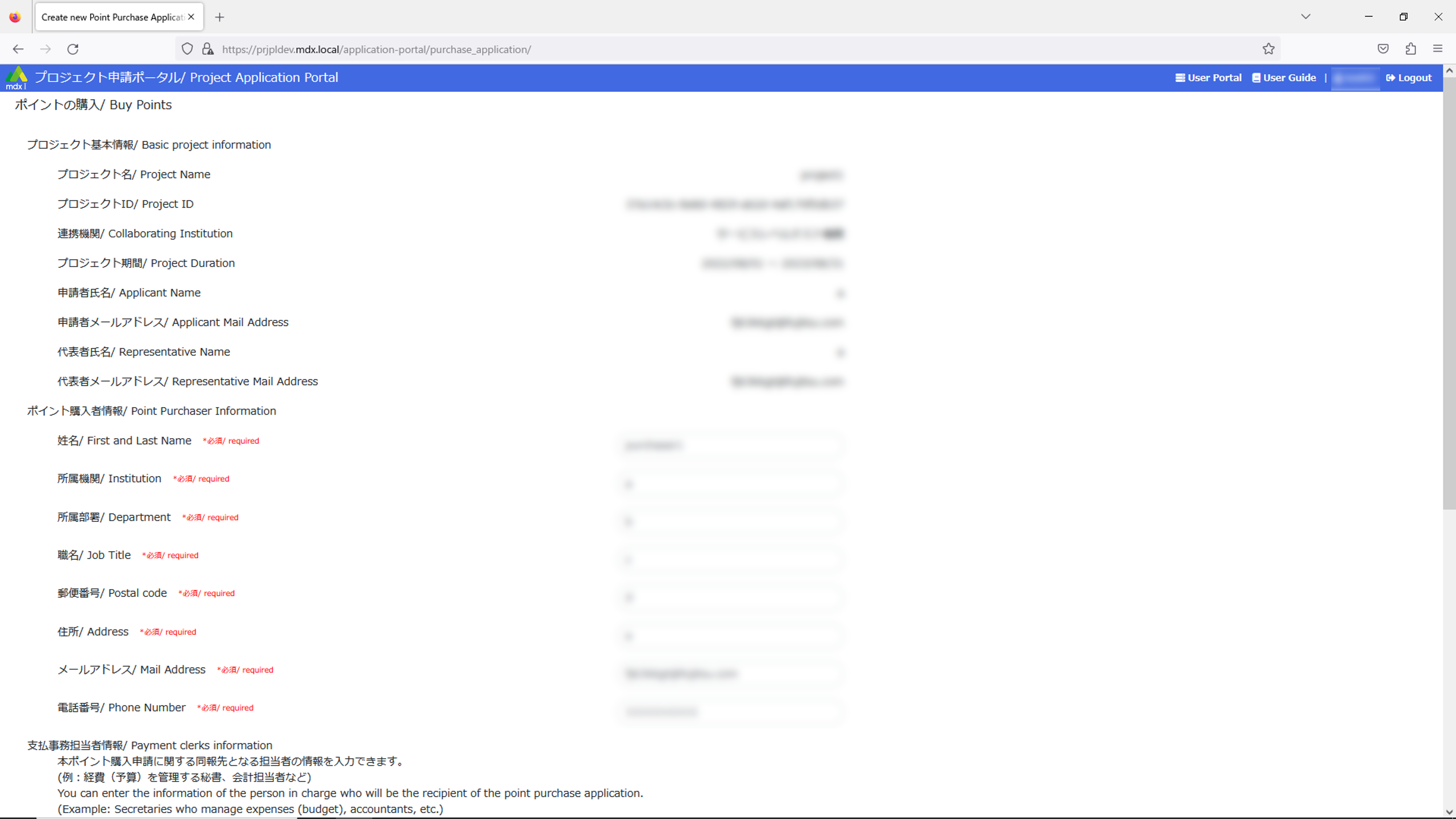
Items marked [必須/ required] must be entered.
For details of entry items for point purchase application: please refer to point purchase application details .
When you have completed the form, click [申請内容を確認する/ Confirm the application] at the bottom left of the application screen.
- If there are any incomplete entries, an error message will be displayed above the application button.Also, the names of items that are incomplete will be displayed in red, so please correct them and click [申請内容を確認する/ Confirm the application] again.
Confirm the details of your point purchase application, and if there are no problems, click on [ポイントの購入を申請する / Application to purchase points].
- The status of your point purchase application will be displayed as [申請中/ Applied] on the point purchase history screen.This completes the point purchase application process.
Point purchase applications can also be made in the following methods.
5.1.1. Cancel the point purchase application and modify/re-apply for the content.
After you cancel application from the point purchase history, you can re-apply for a saved application by restore .
5.2. Add users who can purchase points
5.3. Process payment for purchased points (Credit card payment only)
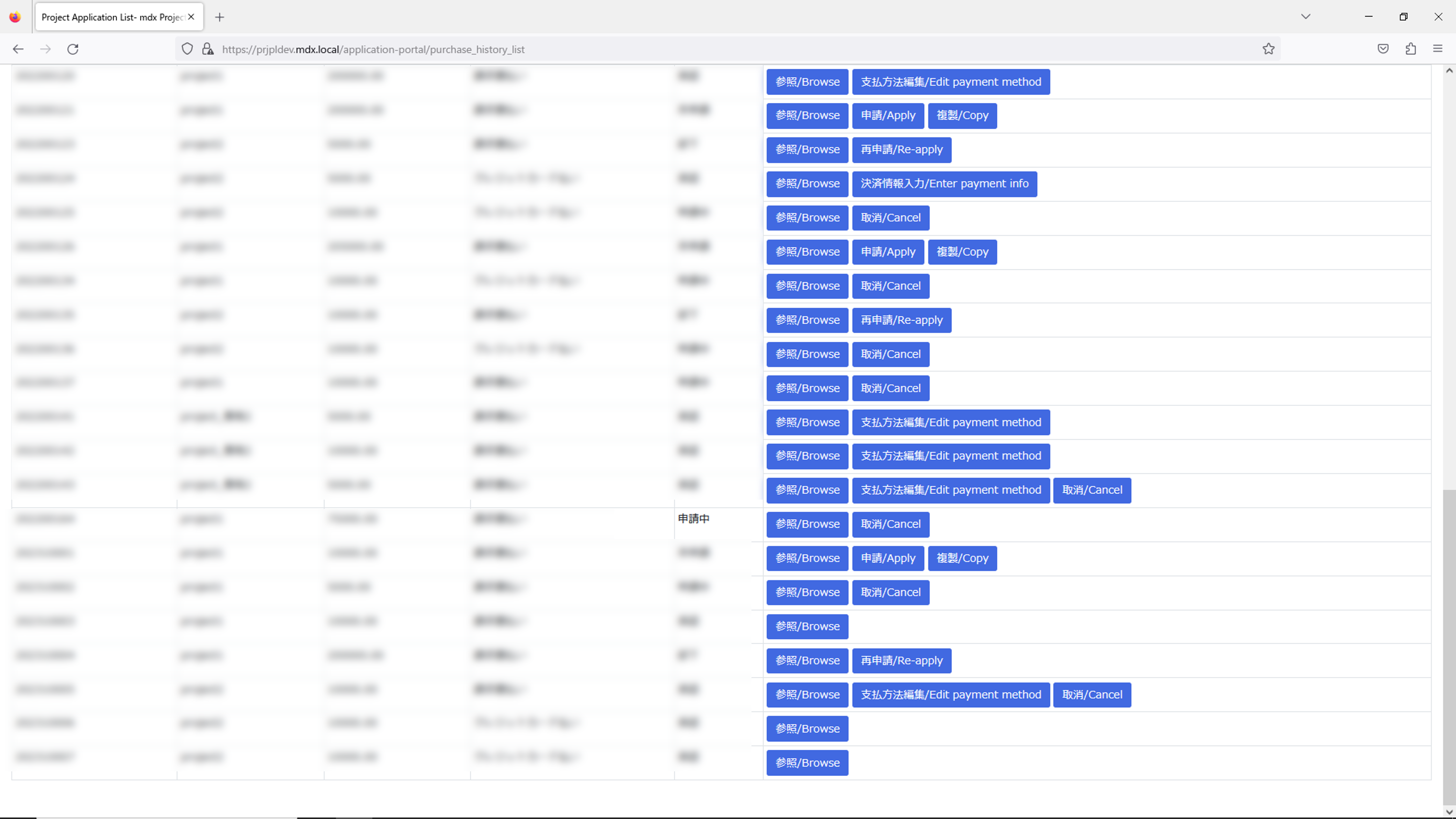
Either of these operations will take you to the point purchase history screen.
Click [移動する/ Move to] on the right of “ポイントの購入履歴を見る/ Confirm point purchase history” on the screen for selecting the function to use.
Click [ポイントの購入履歴を見る/ Confirm point purchase history] on the “プロジェクト申請一覧/ Project Application List” screen.
Click [決済情報入力/ Enter payment info] on the line for the point purchase application to be processed.
To transfer to the point payment screen, confirm the details of the transaction, and if there are no problems, enter the required information in the credit card payment application form.
Click [お申し込み内容確認](Confirm application contents) at the bottom of the input screen.
6. Application process for resources
6.1. Make a resource application
Log in to the User Portal.
Click on [Project] from the top menu.
Click on [PROJECT RESOURCE CHANGE APPLICATION] at the top of list in the main screen.
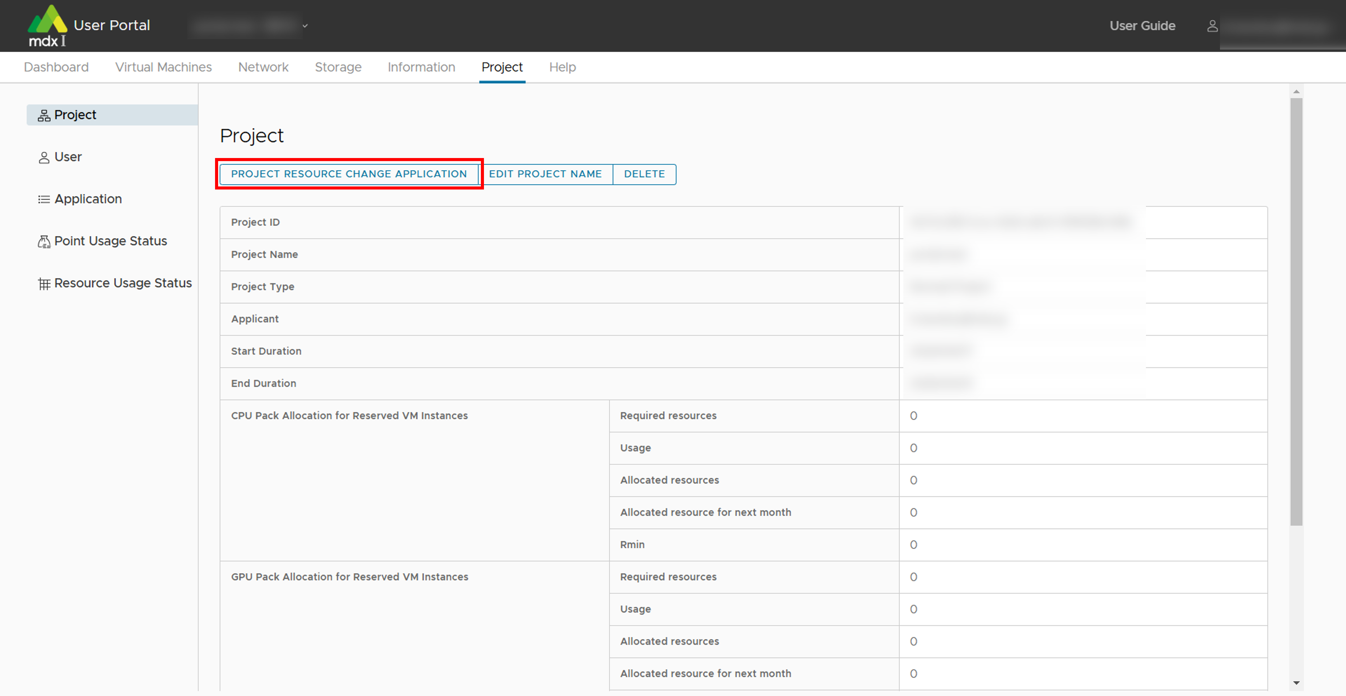
Enter the necessary information and click [APPLY] when completed.
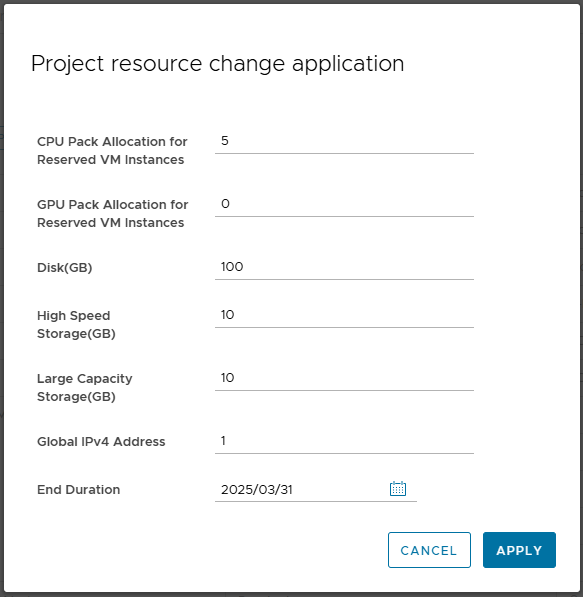
The end date of the project duration can also be changed in this application.
For other project-related confirming/changing functions, please confirm the Functions to confirm and modify projects page.
6.2. Confirm the status of resource application
You can confirm whether the application has been approved or not from Application in the User Portal.
7. Virtual machine usage flow
All operations related to virtual machines are performed from the user portal.
7.1. Confirmation of resource
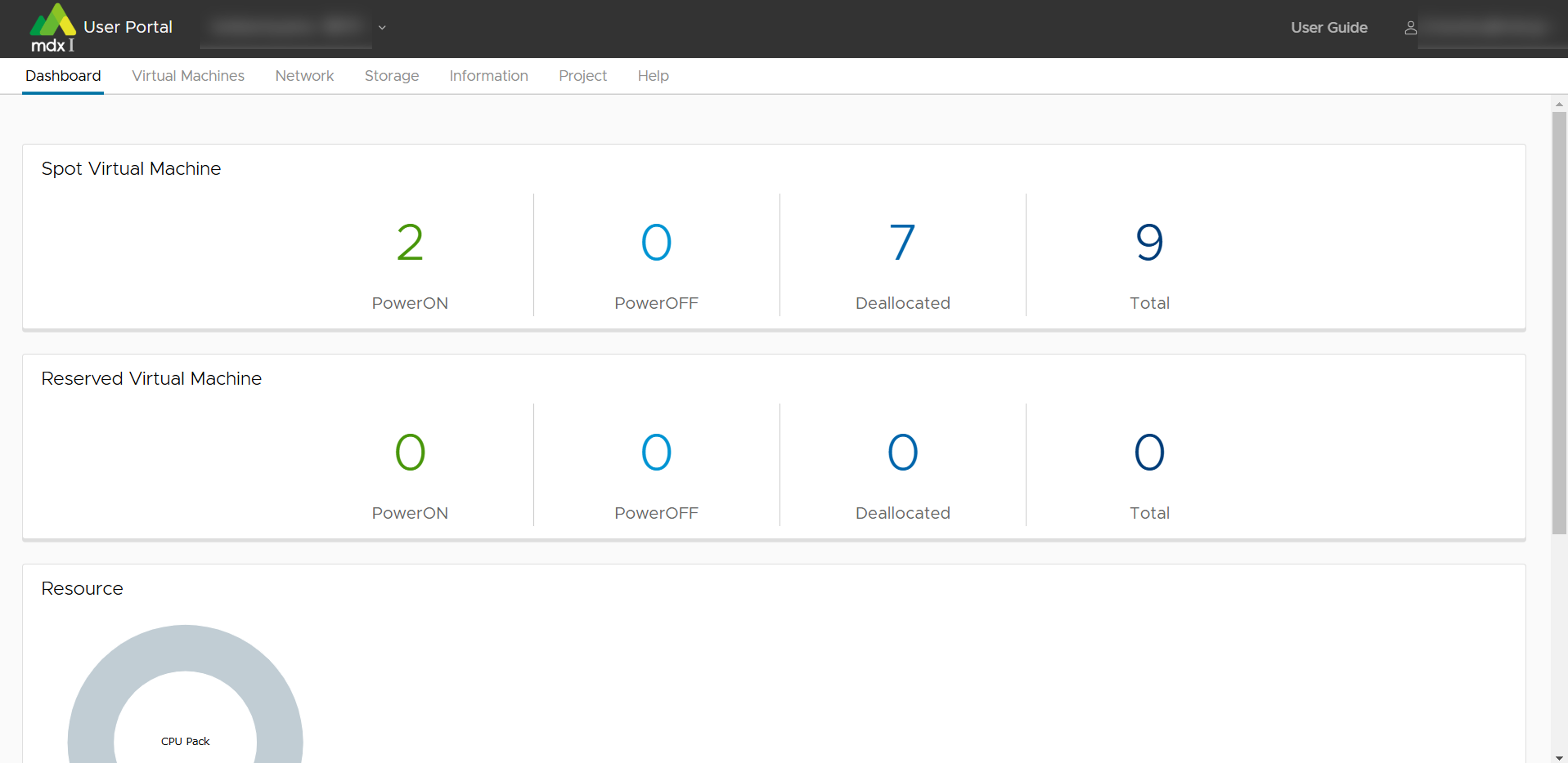
In order to create a virtual machine, resources must remain available for the virtual machine to be created. The dashboard screen shows the power status of virtual machines, resource allocation status, etc.
Dashboard
When you log in to the user portal, you will first see the dashboard screen.
7.2. Creating and starting virtual machine
This section describes the procedures for creating and starting a virtual machine from a virtual machine template or an ISO image that you have prepared yourself.
7.2.1. Create a virtual machine using a virtual machine template
Click on [Virtual Machines] from the top menu.
Click [Deploy] from the side menu.
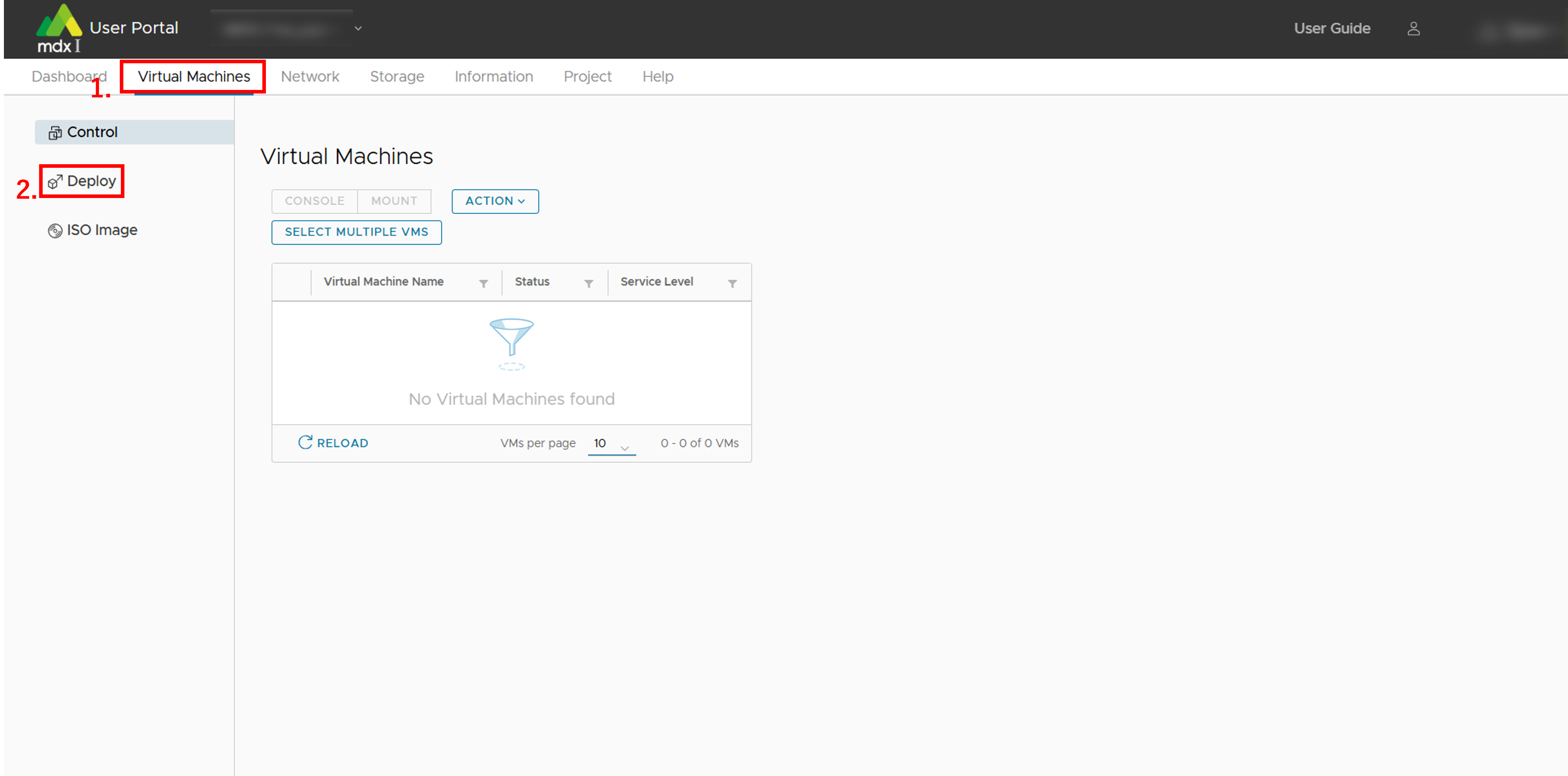
- From the list of virtual machine templates displayed, select a template with any OS name and version,click [DEPLOY] at the top of the list.
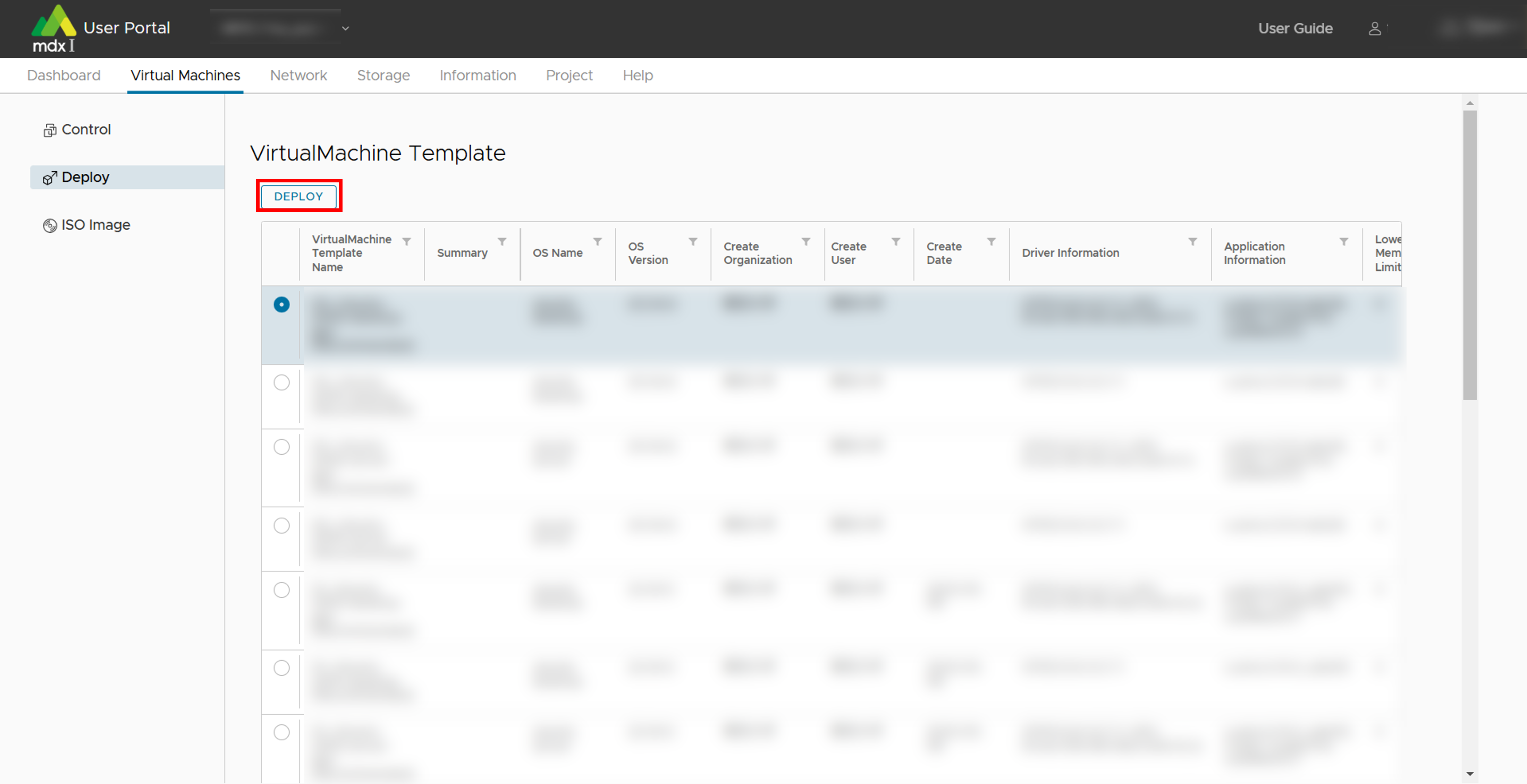
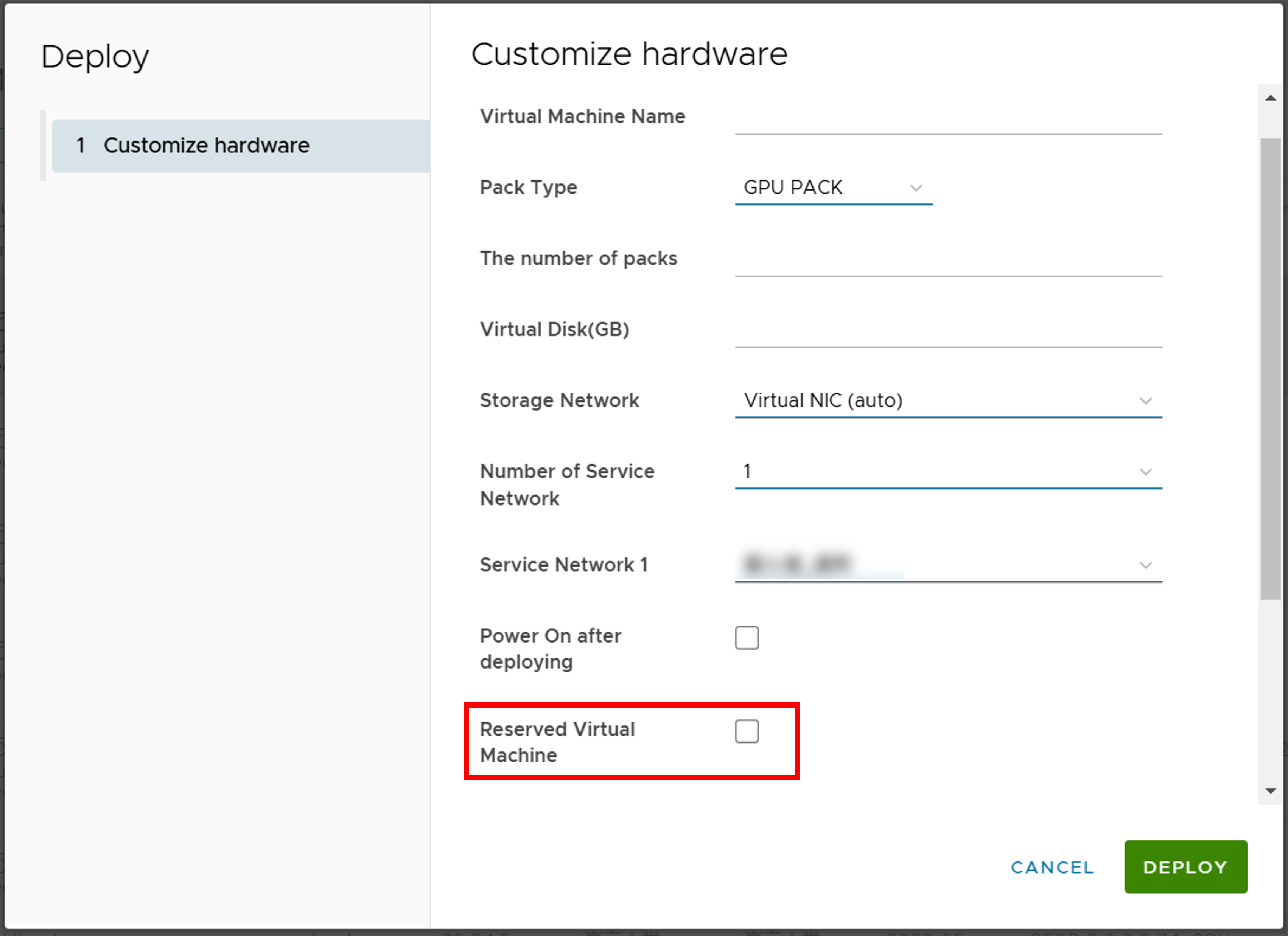
Fill in the required information on the customize hardware screen. Click [DEPLOY] when you are done.
See deployment settings for details.
Please note the displayed [Login username] as you will need it when logging in to the virtual machine.
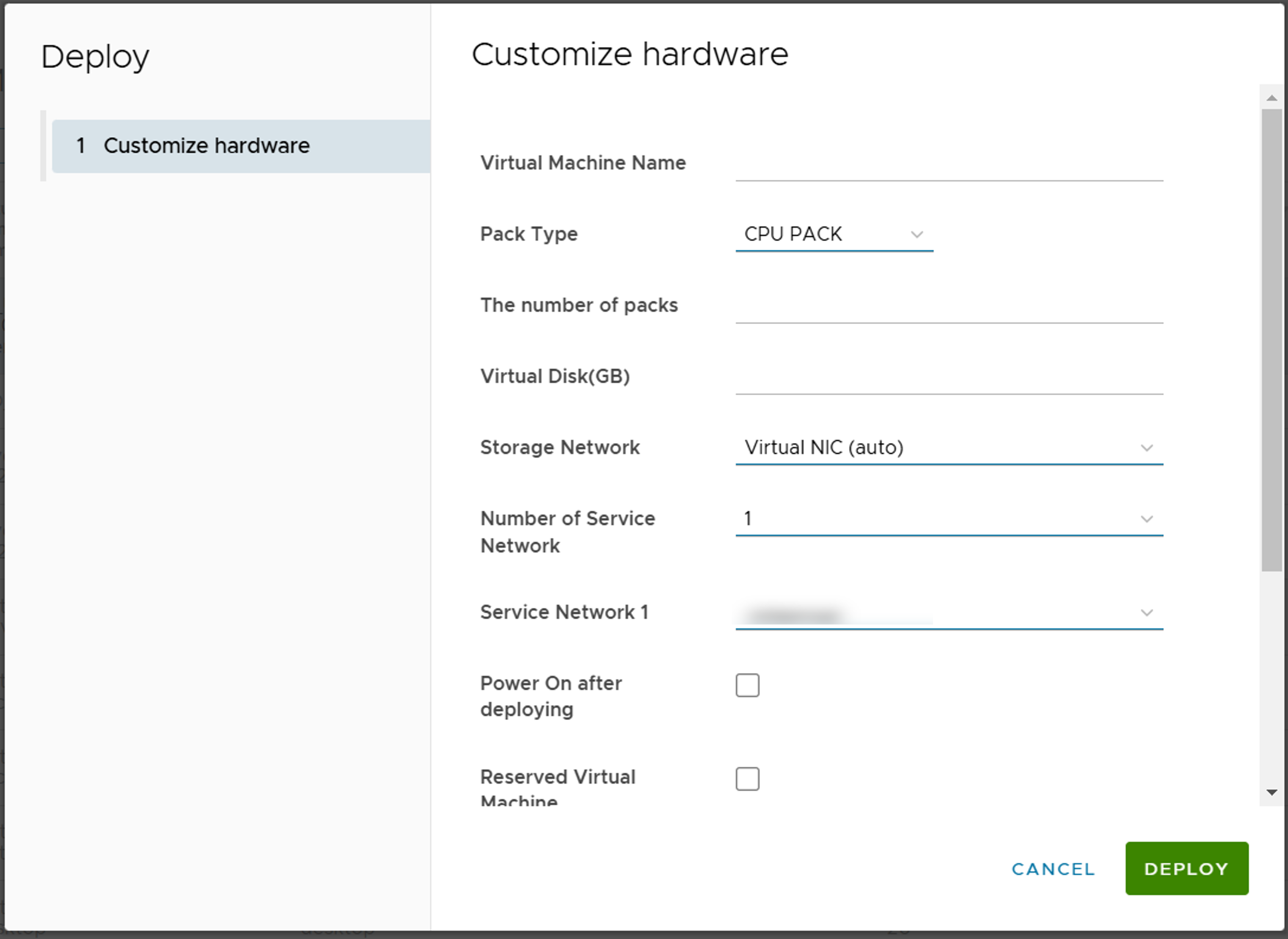
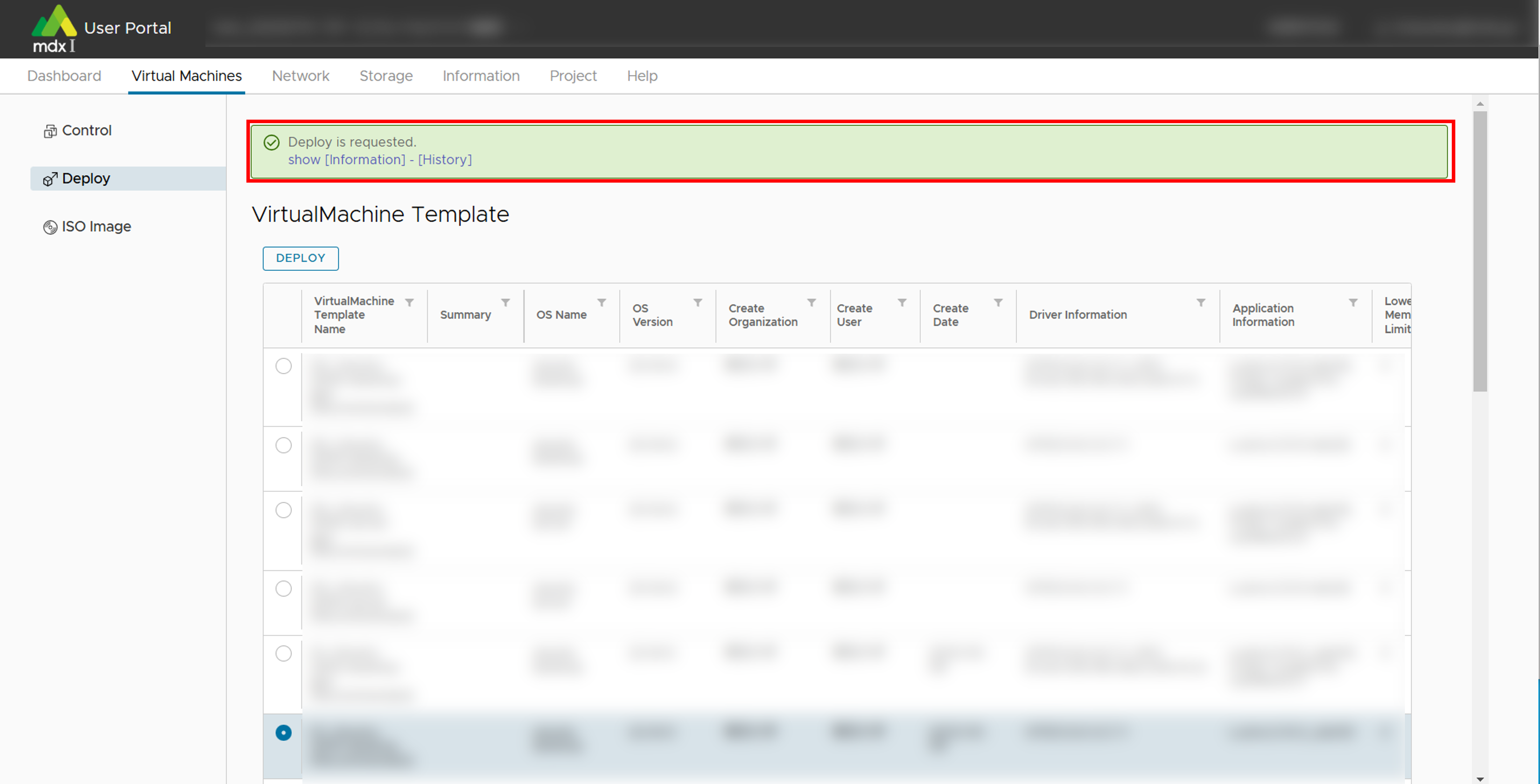
A message indicating that the request has been accepted is displayed at the top of the screen.
Requests take several minutes to complete, depending on the environment.
You can check the progress of your request by clicking the link to the [Indormation]-[History] screen in the message.
If an error message indicating that the request could not be processed is displayed, please contact the institution’s administrator.
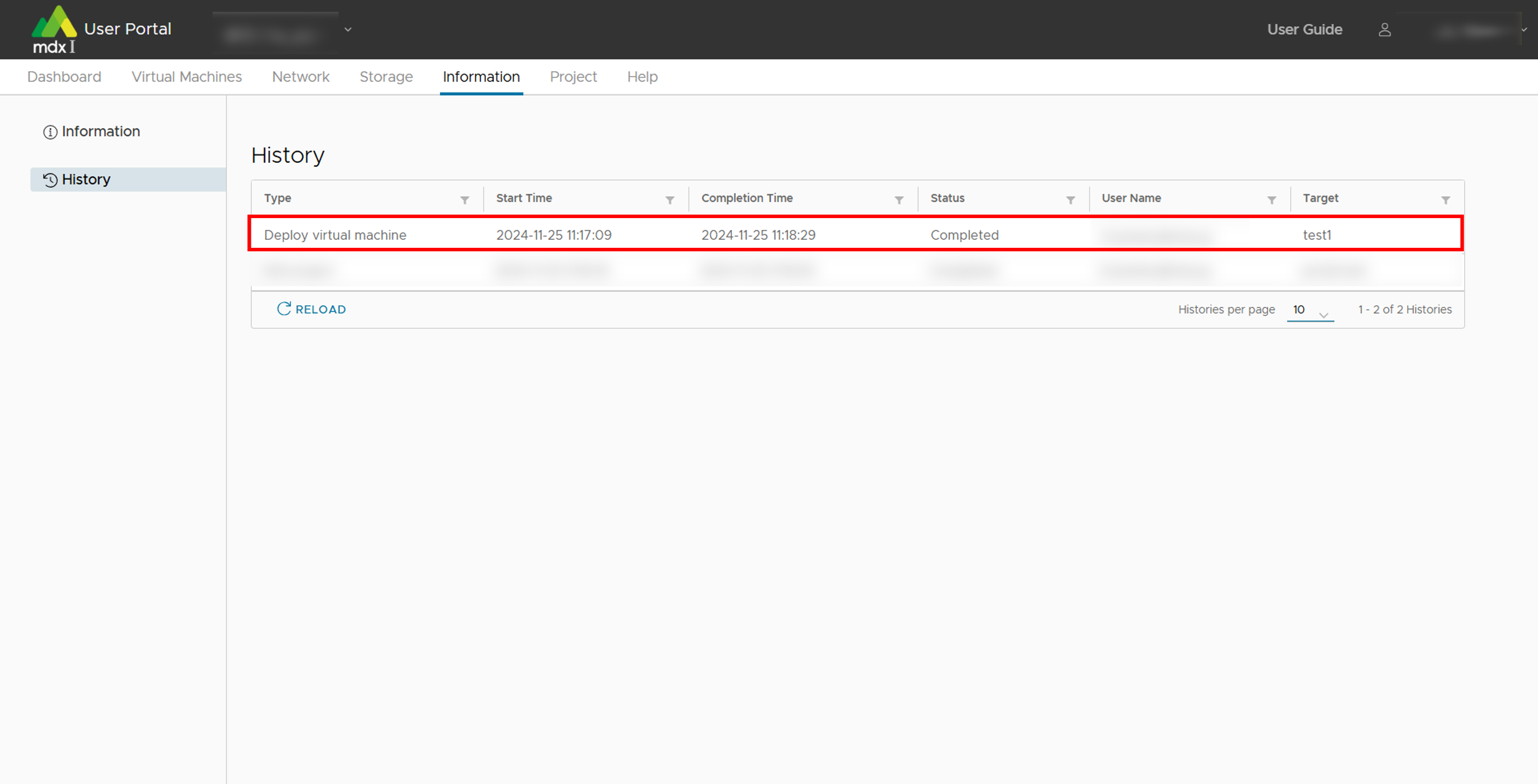
Check the results of your own operations in the status column of the operation history screen.
If the status is [Completed], then proceed to the next step.
If [Failed], please click [>] on the left of the item to see the details of the failure.
Click on [Virtual Machines] from the top menu to return to the virtual machine control screen.
A list of virtual machines will appear on the main screen. Search and select the virtual machine you just created from the list.
If you have not selected [Power On after deploying] when deploying, click [ACTION] > [Power] > [Power On], then click [YES] on the confirmation message.
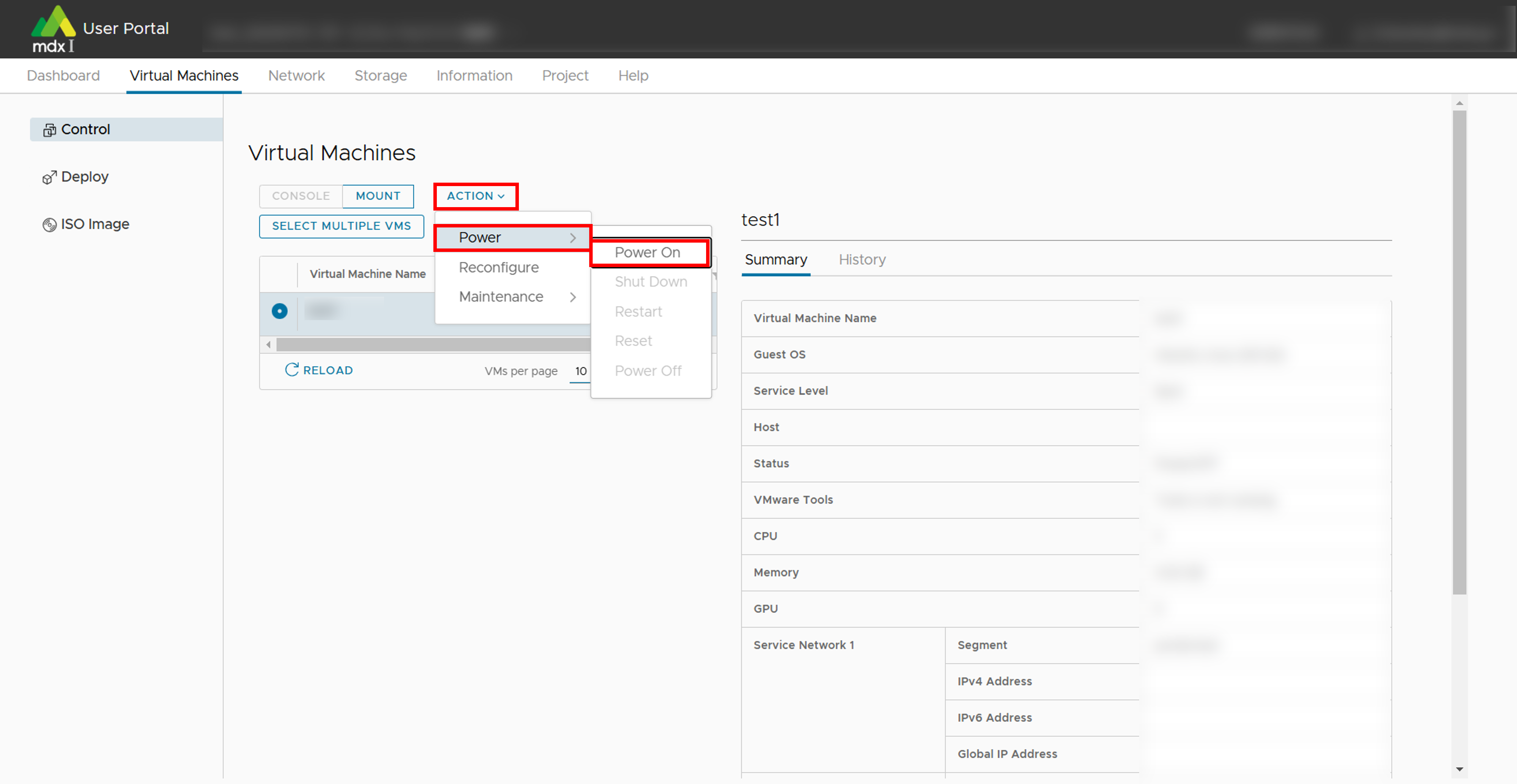
Check the boot status of the virtual machine.
Once the above is confirmed, the startup process is complete.
7.2.2. Create a virtual machine by specifying an ISO image and install an OS
Click on [Virtual Machines] from the top menu.
Click on [ISO Image] from the side menu.
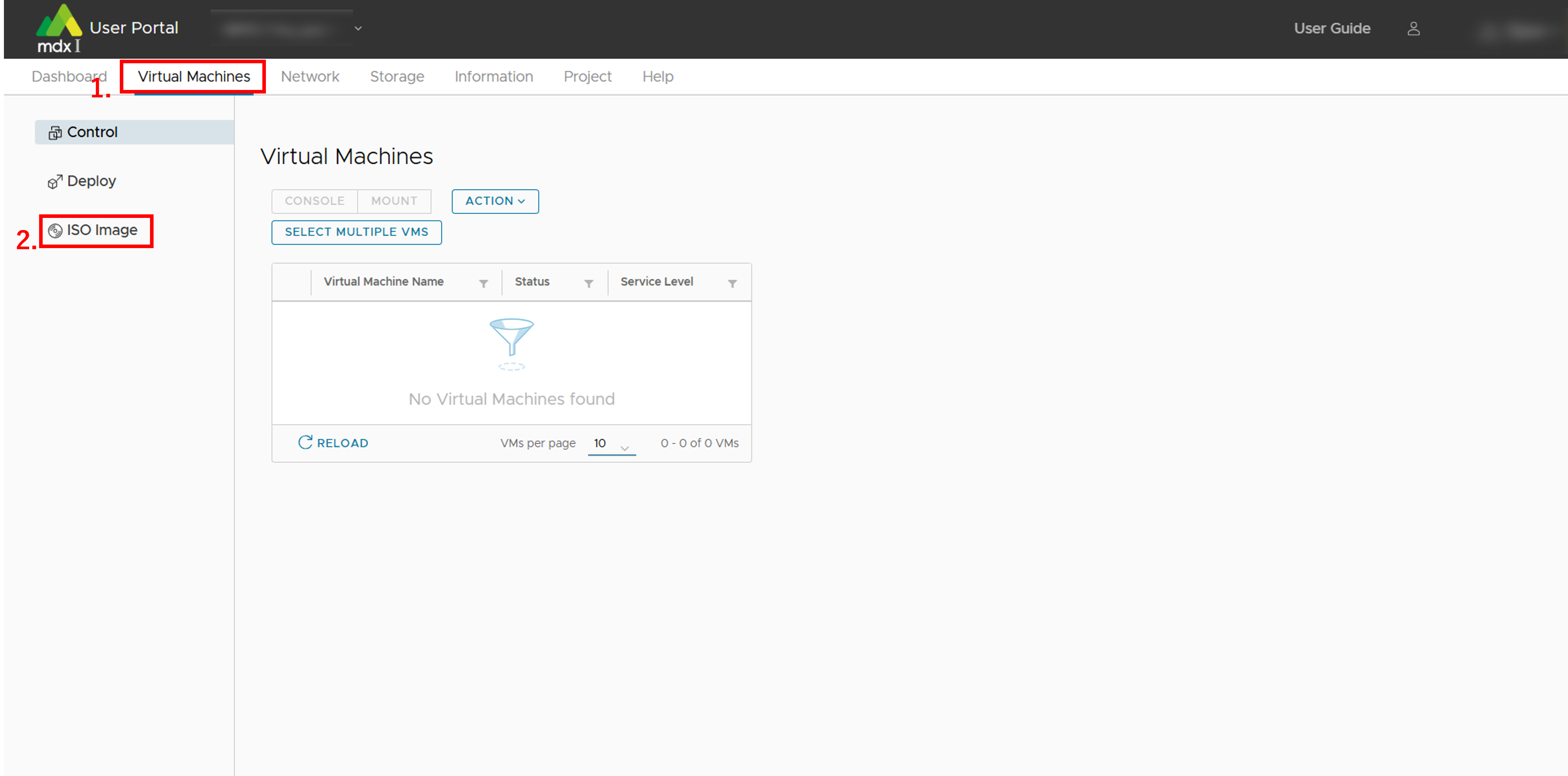
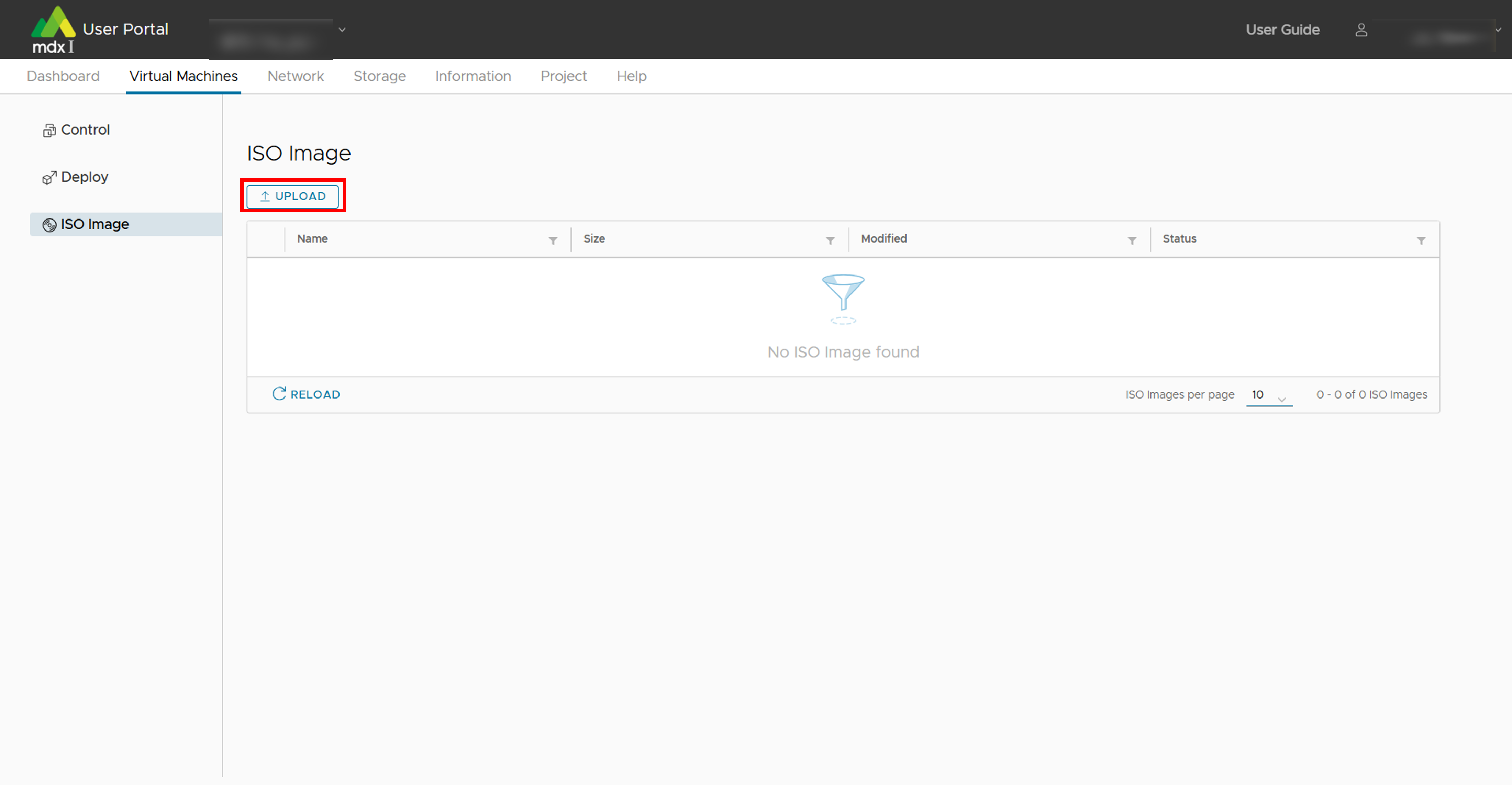
- Check if the ISO image you want to use is uploaded in the list of ISO images displayed.If the file has not been uploaded, click [UPLOAD] at the top of the list.
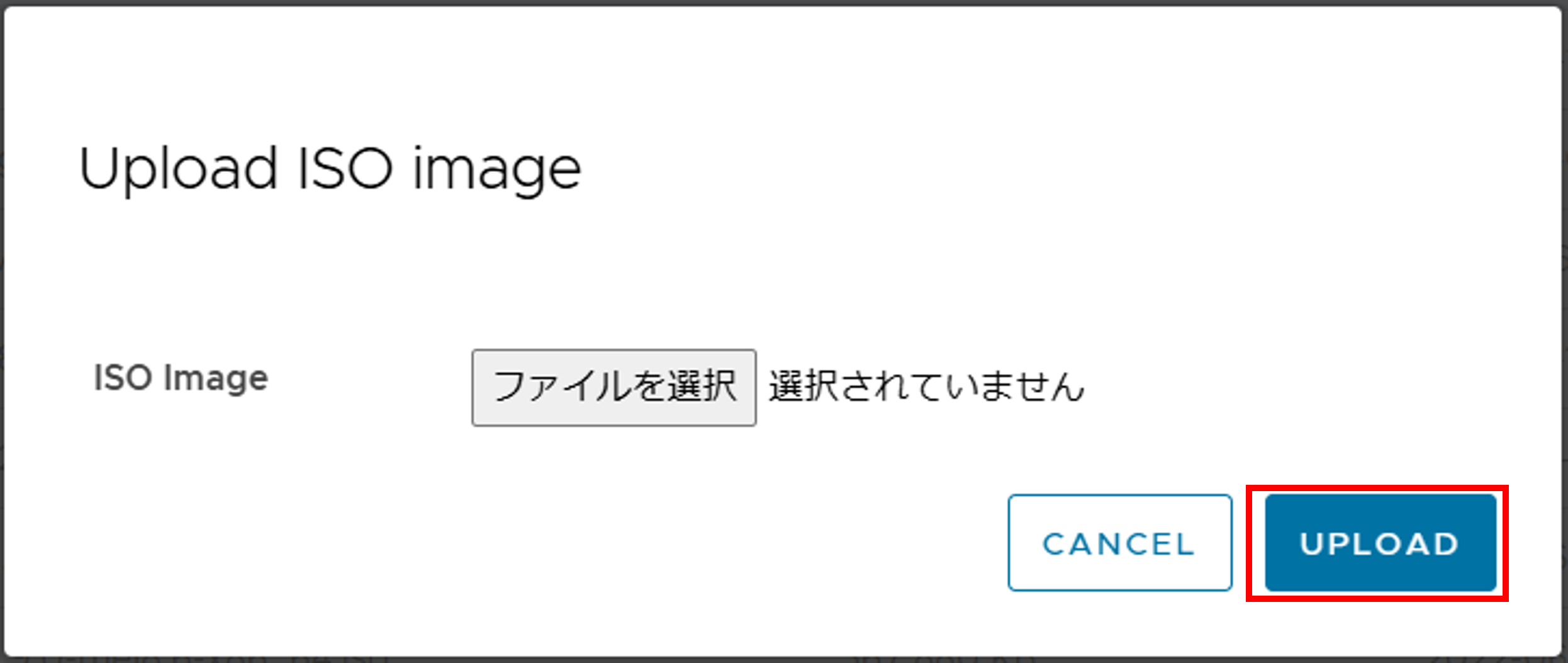
- Select the ISO image you wish to upload from [ISO Image] > [ファイルを選択], and click [UPLOAD].Upload progress can be checked from the operation history screen.
Note
After the upload is complete, click [Deploy] from the side menu.
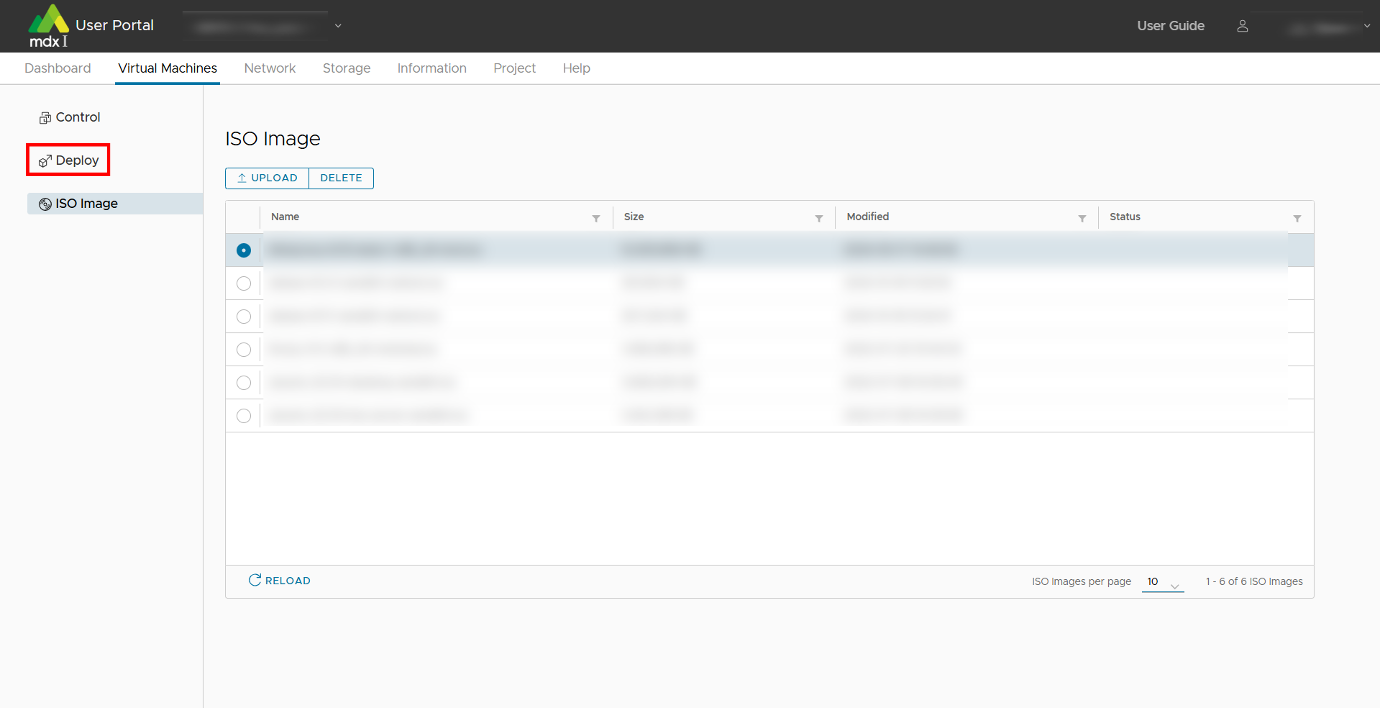
From the list of virtual machine templates displayed, select [ISO_image] and click [DEPLOY] at the top of the list.
Fill in the required information on the customize hardware screen. See deployment settings for details.
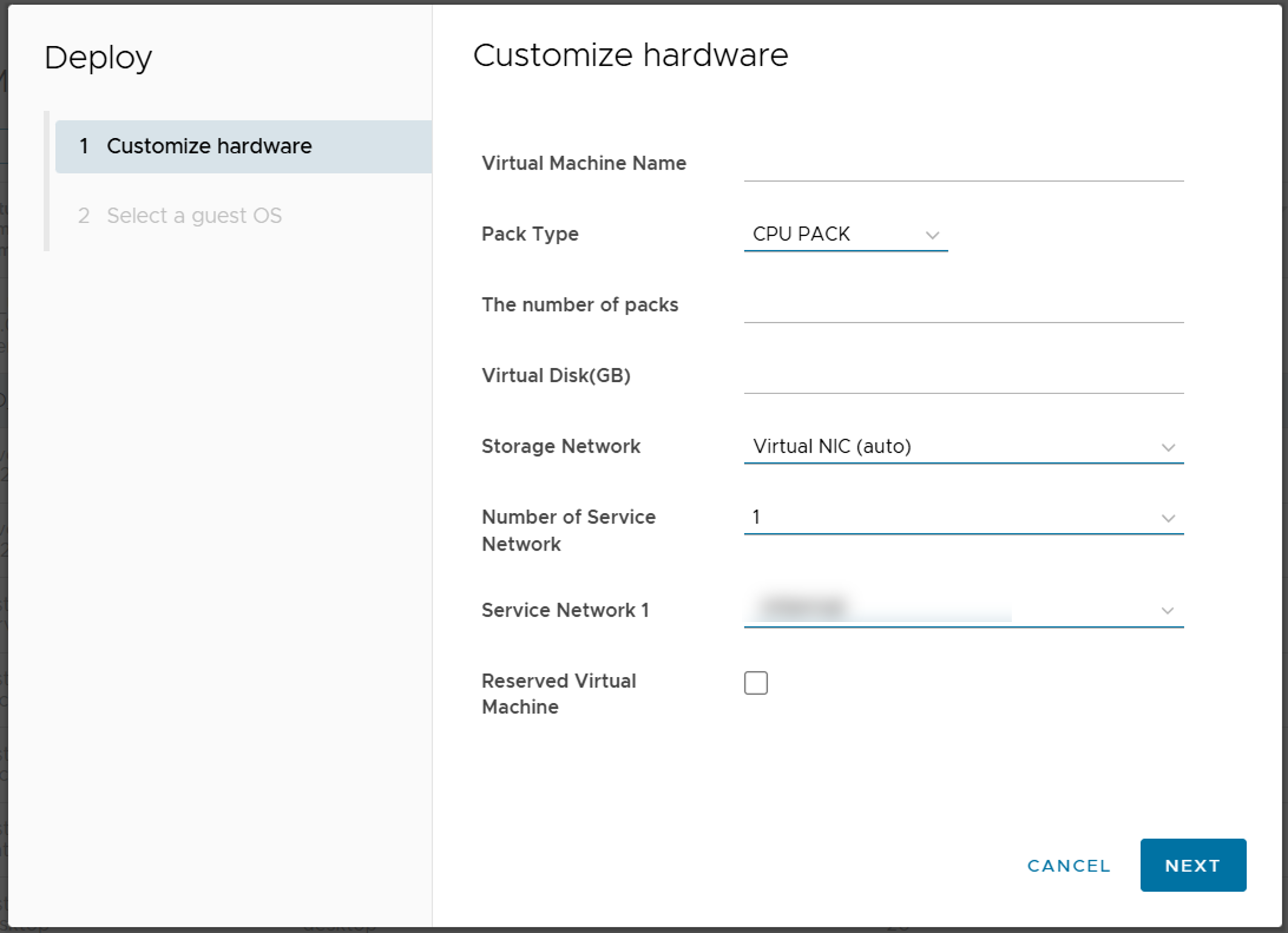
After completing the required information, click [NEXT].
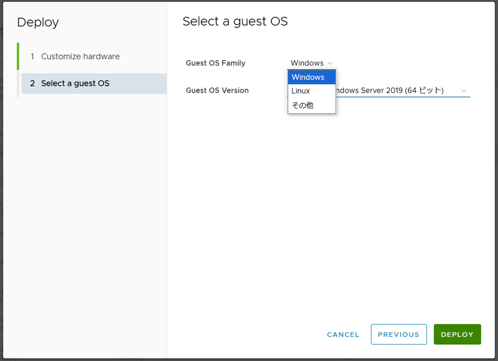
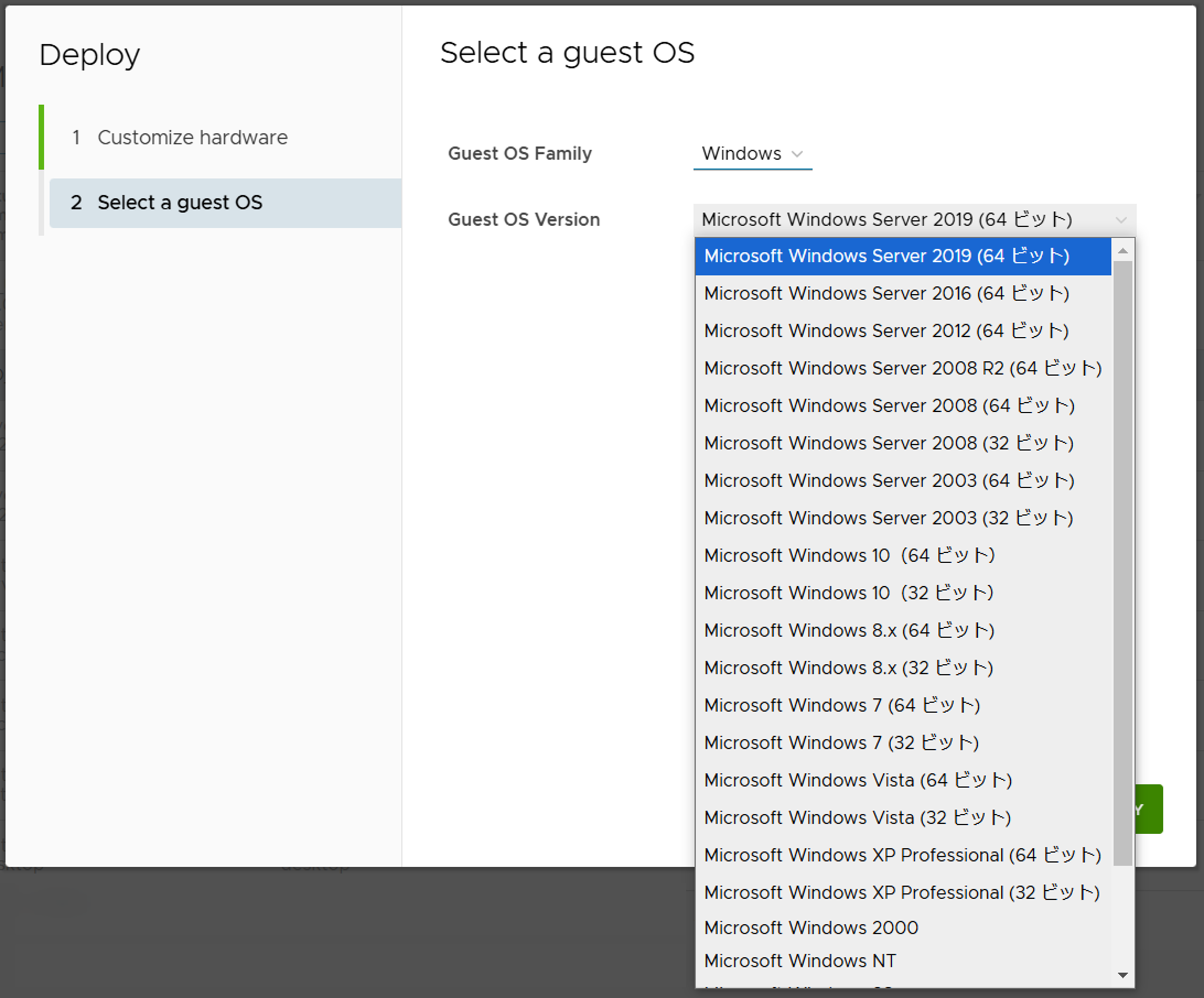
Fill in the required information on the guest OS seletion screen. See deployment settings for details.
If you cannot select any OS version, the hardware version of the template may be affected. If this is the case, please contact your institutional administrator.
Click [DEPLOY] after completing the required information. Deployment progress can be checked from the operation history screen.
After deployment is complete, click on [Virtual Machines] from the top menu to go to the control screen.
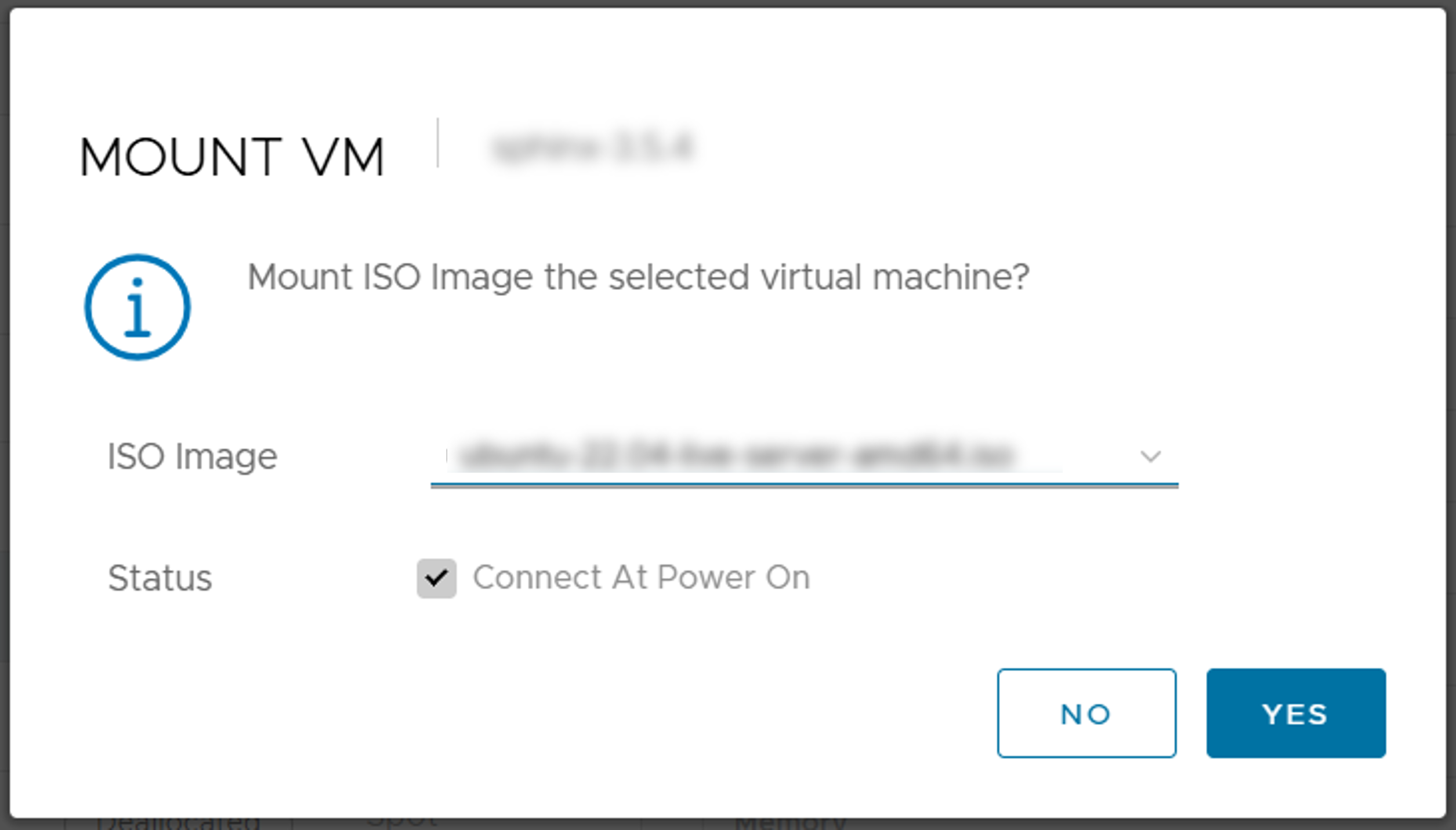
From the list of virtual machines, with the deployed virtual machine selected, click [MOUNT] at the top of the list.
Select the ISO image file to be installed in the virtual machine from the pull-down menu and click [YES].
From [ACTION] at the top of the list, click [Power] > [Power On] and click [YES] on the confirmation message.
Click [CONSOLE] at the top of the list to display the console screen in a separate tab of the browser.
Performs the installation process for each OS on the console screen.
After the installation is complete, confirm that the IP address (Service network) of the virtual machine has been obtained in the summary on the right side of the screen on the User Portal.
Once the above is confirmed, the startup process is complete.
7.3. Configure network information to access virtual machines
In order to access a virtual machine, it is necessary to configure settings for the network that will access the virtual machine.
7.3.1. ACL (Access control list) settings
Refer to How to configure ACLs for details.
7.3.2. DNAT (Destination NAT) configuration
See How to configure DNAT for details.
7.4. Accessing Virtual Machine
7.4.1. When accessing a virtual machine managed by another member
Global IP address of the virtual machine
Username
If not public key authentication, password
7.5. Mount High-Speed Storage and Large-Capacity Storage
7.5.1. For virtual machines created from the virtual machine template
For virtual machines created from the following virtual machine template, Lustre Client configuration is required.
01_Ubuntu-2204-desktop-gpu (Recommended)
01_Ubuntu-2204-desktop (Recommended)
01_Ubuntu-2204-server-gpu (Recommended)
01_Ubuntu-2204-server (Recommended)
02_cluster-pack-client
02_cluster-pack-server
02_MateriApps-live
If you use a virtual machine template other than the ones mentioned above, Lustre will be mounted automatically, so Lustre Client configuration is not required.
Install OFED driver
It is already installed, so no work is needed.
Install Lustre Client
It is already installed, so no work is needed.
Configure Lustre Client
Deploy /etc/lnet.conf.ddn and modify it
Rename /etc/lnet.conf.ddn.j2 to /etc/lnet.conf.ddn.$ sudo mv /etc/lnet.conf.ddn.j2 /etc/lnet.conf.ddn
Modify the configuration file.Modify the IP address of nid and the device name of interfaces within the blocks of “- net type: o2ib10” and “- net type: tcp10”.Replace {{ ib_src_ipaddr }} and {{ tcp_src_ipaddr }} with the IPv4 address of “Storage Network 1”.Replace {{ ib_netif }} and {{ tcp_netif }} with the network interface (ens*) of “storage network 1”.To check the device name of the “Storage Network 1” interface, open a terminal on the virtual machine and execute the command “ip -br addr”.The item output in the first column of the line where the IP address of “Storage Network 1” is displayed in the output of the above command is the network interface name.Example: If the IP address of “Storage Network 1” is “10.134.82.79/21”,In the following executable example, “ens194” is the network interface name for “storage network 1”.$ ip -br addr lo UNKNOWN 127.0.0.1/8 ::1/128 ens163 UP 10.aaa.bbb.ccc/21 2001:2f8:1041:223:9ba2:6ea9:3fd4:d289/64 fe80::d707:ca60:98a:cfb2/64 ens194 UP 10.134.82.79/21 fe80::698:e5e1:3574:f2e6/64
Below is an example of the change when the IP address is “10.134.82.79” and the network interface name is “ens194”.
Before modification:
- net type: o2ib10 local NI(s): - nid: {{ ib_src_ipaddr }}@o2ib10 status: up interfaces: 0: {{ ib_netif }} - net type: tcp10 local NI(s): - nid: {{ tcp_src_ipaddr }}@tcp10 status: up interfaces: 0: {{ tcp_netif }}
After modification:
- net type: o2ib10 local NI(s): - nid: 10.134.82.79@o2ib10 status: up interfaces: 0: ens194 - net type: tcp10 local NI(s): - nid: 10.134.82.79@tcp10 status: up interfaces: 0: ens194
Modify /etc/fstab
If you select “Virtual NIC (auto)” for the type of storage network, uncomment the two lines for lustre (tcp). If you select “SR-IOV”, uncomment the two lines for lustre (rdma).
The following describes the case where the storage network type “SR-IOV” is selected.
Before modification:
# lustre (tcp) #172.17.8.40@tcp10:172.17.8.41@tcp10:/fast /fast lustre network=tcp10,flock,noauto,defaults 0 0 #172.17.8.56@tcp10:172.17.8.57@tcp10:/large /large lustre network=tcp10,flock,noauto,defaults 0 0 # lustre (rdma) #172.17.8.40@o2ib10:172.17.8.41@o2ib10:/fast /fast lustre network=o2ib10,flock,noauto,defaults 0 0 #172.17.8.56@o2ib10:172.17.8.57@o2ib10:/large /large lustre network=o2ib10,flock,noauto,defaults 0 0
After modification:
# lustre (tcp) #172.17.8.40@tcp10:172.17.8.41@tcp10:/fast /fast lustre network=tcp10,flock,noauto,defaults 0 0 #172.17.8.56@tcp10:172.17.8.57@tcp10:/large /large lustre network=tcp10,flock,noauto,defaults 0 0 # lustre (rdma) 172.17.8.40@o2ib10:172.17.8.41@o2ib10:/fast /fast lustre network=o2ib10,flock,noauto,defaults 0 0 172.17.8.56@o2ib10:172.17.8.57@o2ib10:/large /large lustre network=o2ib10,flock,noauto,defaults 0 0
Modify /etc/modprobe.d/lustre.conf
This modification is required when “Virtual NIC (auto)” is selected as the storage network type.If “SR-IOV” is selected as the storage network type, no modification is required.Before modification:
options lnet lnet_peer_discovery_disabled=1 options lnet lnet_transaction_timeout=100 # lustre (tcp) #options ksocklnd rx_buffer_size=16777216 #options ksocklnd tx_buffer_size=16777216
After modification:
options lnet lnet_peer_discovery_disabled=1 options lnet lnet_transaction_timeout=100 # lustre (tcp) options ksocklnd rx_buffer_size=16777216 options ksocklnd tx_buffer_size=16777216
Configure the Lustre client service to start automatically and restart the virtual machine.
$ sudo systemctl enable lustre_client $ sudo rebootAfter reboot, /large and /fast are mounted as lustre storage.
7.5.2. Without virtual machine template (Rocky Linux 8)
The OS is assumed to be Rocky Linux release 8.10 (Rocky-8.10-x86_64-dvd1.iso: Obtained from official page , etc.).
- Install OFED driverFrom the Mellanox web, download the OFED driver ISO image “MLNX_OFED_LINUX-23.10-5.1.4.0-rhel8.10-x86_64.iso”.Mount the ISO image and run the installation script. At this time, specify “–guest (For VM guest OS)”.
# mount -o ro,loop MLNX_OFED_LINUX-23.10-5.1.4.0-rhel8.10-x86_64.iso /mnt # cd /mnt # ./mlnxofedinstall --guest
If there are packages included in the OS that are not installed in the environment, the installation of OFED may fail.In that case, please install those packages from the OS ISO image.(Do not apply the latest packages released on the Internet). - Get Lustre Client source and configuration file templatesSource program files for Lustre Client provided by DDN and various configuration file templates for Lustre Client are obtained from a web server accessible only from within mdx.
lustre-2.14.0_ddn198.tar.gz
lustre_config_rocky_rdma.tgz (if using rdma)
lustre_config_rocky_tcp.tgz (if using tcp)
# wget http://172.16.2.26/lustre-2.14.0_ddn198.tar.gz # wget http://172.16.2.26/lustre_config_rocky_rdma.tgz # wget http://172.16.2.26/lustre_config_rocky_tcp.tgz
- Lustre Client package buildUnpack the obtained source program and build the package.
# dnf install gcc-gfortran libtool libmount-devel libyaml-devel json-c-devel rpm-build kernel-rpm-macros kernel-abi-whitelists # tar zxf lustre-2.14.0_ddn198.tar.gz # cd lustre-2.14.0_ddn198 # LANG=C # sh autogen.sh # ./configure --with-o2ib=/usr/src/ofa_kernel/default --disable-server --disable-lru-resize # make rpms
- Install Lustre ClientInstall following two from the packages you have created.
# rpm -ivh kmod-lustre-client-2.14.0_ddn198-1.el8.x86_64.rpm lustre-client-2.14.0_ddn198-1.el8.x86_64.rpm - Configure Lustre ClientModify and deploy various files using the obtained configuration file templates.
- /etc/fstabAdd an entry for Lustre Filesystem to /etc/fstab.
If SR-IOV is used, add the following line to fstab.
172.17.8.40@o2ib10:172.17.8.41@o2ib10:/fast /fast lustre network=o2ib10,flock,noauto,defaults 0 0 172.17.8.56@o2ib10:172.17.8.57@o2ib10:/large /large lustre network=o2ib10,flock,noauto,defaults 0 0
To use a regular virtual NIC (VMXNET3), add the following line to fstab”
172.17.8.40@tcp10:172.17.8.41@tcp10:/fast /fast lustre network=tcp10,flock,noauto,defaults 0 0 172.17.8.56@tcp10:172.17.8.57@tcp10:/large /large lustre network=tcp10,flock,noauto,defaults 0 0
- /etc/lnet.conf.ddnCopy etc/lnet.conf.ddn to /etc/lnet.conf.ddn and modify it to suit your environment.Modify the IP address of nid and the device name of interfaces within the blocks of “- net type: o2ib10” and “- net type: tcp10”.To check the device name of the “Storage Network 1” interface, open a terminal on the virtual machine and execute the command “ip -br addr”.The item output in the first column of the line where the IP address of “Storage Network 1” is displayed in the output of the above command is the network interface name.Example: If the IP address of “Storage Network 1” is “10.134.82.79/21”,In the following executable example, “ens194” is the network interface name for “storage network 1”.
$ ip -br addr
lo               UNKNOWN        127.0.0.1/8 ::1/128
ens163           UP             10.aaa.bbb.ccc/21 2001:2f8:1041:223:9ba2:6ea9:3fd4:d289/64 fe80::d707:ca60:98a:cfb2/64
ens194           UP             10.134.82.79/21 fe80::698:e5e1:3574:f2e6/64
Below is an example of the change when the IP address is “10.134.82.79” and the network interface name is “ens194”.
Before modification:
- net type: o2ib10 local NI(s): - nid: 172.17.8.32@o2ib10 status: up interfaces: 0: enp59s0f0 - net type: tcp10 local NI(s): - nid: 172.17.8.32@tcp10 status: up interfaces: 0: enp59s0f0
After modification:
- net type: o2ib10
  local NI(s):
    - nid: 10.134.82.79@o2ib10
      status: up
      interfaces:
          0: ens194
- net type: tcp10
  local NI(s):
    - nid: 10.134.82.79@tcp10
      status: up
      interfaces:
          0: ens194
- /etc/sysconfig/lustre_clientCopy etc/sysconfig/lustre_client to /etc/sysconfig/lustre_client.
- /etc/modprobe.d/lustre.confCopy etc/modprobe.d/lustre.conf to /etc/modprobe.d/lustre.conf.
- /etc/init.d/lustre_clientCopy etc/init.d/lustre_client to /etc/init.d/lustre_client.
- /usr/lib/systemd/system/lustre_client.serviceCopy usr/lib/systemd/system/lustre_client.service to /usr/lib/systemd/system/lustre_client.service.
Configure the Lustre client service to start automatically and restart the virtual machine.
$ sudo systemctl enable lustre_client
$ sudo reboot
After reboot, /large and /fast are mounted as lustre storage.
7.5.3. Without virtual machine template (Rocky Linux 9)
The OS is assumed to be Rocky Linux release 9.7 (Rocky-9.7-x86_64-dvd.iso: Obtained from official page , etc.)
- Install OFED driverFrom the NVIDIA web, download and install the OFED driver RPM.
# wget https://www.mellanox.com/downloads/DOCA/DOCA_v3.3.0/host/doca-host-3.3.0-088000_26.01_rhel9.x86_64.rpm # rpm -i doca-host-3.3.0-088000_26.01_rhel9.x86_64.rpm # dnf clean all # dnf -y install doca-ofed
If there are packages included in the OS that are not installed in the environment, the installation of OFED may fail.In that case, please install those packages from the OS ISO image.(Do not apply the latest packages released on the Internet). - Get Lustre Client source and configuration file templatesSource program files for Lustre Client provided by DDN and various configuration file templates for Lustre Client are obtained from a web server accessible only from within mdx.
lustre-2.14.0_ddn242.tar.gz
lustre-2.14.0_ddn242.rocky.patch
lustre_config_rocky_rdma.tgz (if using rdma)
lustre_config_rocky_tcp.tgz (if using tcp)
# wget http://172.16.2.26/lustre-2.14.0_ddn242.tar.gz # wget http://172.16.2.26/lustre-2.14.0_ddn242.rocky.patch # wget http://172.16.2.26/lustre_config_rocky_rdma.tgz # wget http://172.16.2.26/lustre_config_rocky_tcp.tgz
- Lustre Client package buildUnpack the obtained source program and build the package.
# dnf install libtool keyutils-libs-devel libmount-devel rpm-build kernel-abi-stablelists kernel-rpm-macros initscripts # dnf --enablerepo=devel install libyaml-devel json-c-devel # tar zxf lustre-2.14.0_ddn242.tar.gz # cd lustre-2.14.0_ddn242 # patch -p1 < ../lustre-2.14.0_ddn242.rocky.patch # LANG=C # sh autogen.sh # ./configure --with-o2ib=/usr/src/ofa_kernel/x86_64/$(uname -r) --disable-server --disable-lru-resize # make rpms # make dkms-rpms
- Install Lustre ClientInstall following two from the packages you have created.
# dnf install lustre-client-2.14.0_ddn242-1.el9.x86_64.rpm lustre-client-dkms-2.14.0_ddn242-1.el9.noarch.rpm - Configure Lustre ClientModify and deploy various files using the obtained configuration file templates.
- /etc/fstabAdd an entry for Lustre Filesystem to /etc/fstab.
If SR-IOV is used, add the following line to fstab.
172.17.8.40@o2ib10:172.17.8.41@o2ib10:/fast /fast lustre network=o2ib10,flock,noauto,defaults 0 0 172.17.8.56@o2ib10:172.17.8.57@o2ib10:/large /large lustre network=o2ib10,flock,noauto,defaults 0 0
To use a regular virtual NIC (VMXNET3), add the following line to fstab”
172.17.8.40@tcp10:172.17.8.41@tcp10:/fast /fast lustre network=tcp10,flock,noauto,defaults 0 0 172.17.8.56@tcp10:172.17.8.57@tcp10:/large /large lustre network=tcp10,flock,noauto,defaults 0 0
- /etc/lnet.conf.ddnCopy etc/lnet.conf.ddn to /etc/lnet.conf.ddn and modify it to suit your environment.Modify the IP address of nid and the device name of interfaces within the blocks of “- net type: o2ib10” and “- net type: tcp10”.To check the device name of the “Storage Network 1” interface, open a terminal on the virtual machine and execute the command “ip -br addr”.The item output in the first column of the line where the IP address of “Storage Network 1” is displayed in the output of the above command is the network interface name.Example: If the IP address of “Storage Network 1” is “10.134.82.79/21”,In the following executable example, “ens194” is the network interface name for “storage network 1”.
$ ip -br addr lo UNKNOWN 127.0.0.1/8 ::1/128 ens163 UP 10.aaa.bbb.ccc/21 2001:2f8:1041:223:9ba2:6ea9:3fd4:d289/64 fe80::d707:ca60:98a:cfb2/64 ens194 UP 10.134.82.79/21 fe80::698:e5e1:3574:f2e6/64
Below is an example of the change when the IP address is “10.134.82.79” and the network interface name is “ens194”.
Before modification:
- net type: o2ib10 local NI(s): - nid: 172.17.8.32@o2ib10 status: up interfaces: 0: enp59s0f0 - net type: tcp10 local NI(s): - nid: 172.17.8.32@tcp10 status: up interfaces: 0: enp59s0f0
After modification:
- net type: o2ib10 local NI(s): - nid: 10.134.82.79@o2ib10 status: up interfaces: 0: ens194 - net type: tcp10 local NI(s): - nid: 10.134.82.79@tcp10 status: up interfaces: 0: ens194
- /etc/sysconfig/lustre_clientCopy etc/sysconfig/lustre_client to /etc/sysconfig/lustre_client.
- /etc/modprobe.d/lustre.confCopy etc/modprobe.d/lustre.conf to /etc/modprobe.d/lustre.conf.
- /etc/init.d/lustre_clientCopy etc/init.d/lustre_client to /etc/init.d/lustre_client.
- /usr/lib/systemd/system/lustre_client.serviceCopy usr/lib/systemd/system/lustre_client.service to /usr/lib/systemd/system/lustre_client.service.
Configure the Lustre client service to start automatically and restart the virtual machine.
$ sudo systemctl enable lustre_client $ sudo rebootAfter reboot, /large and /fast are mounted as lustre storage.
7.5.4. Without virtual machine template (ubuntu20.04)
- Install OFED driverObtain the ISO image “MLNX_OFED_LINUX-5.8-5.1.1.2-ubuntu20.04-x86_64.iso” for OFED driver from the Mellanox web.Mount the ISO image and run the installation script. At this time, specify “–guest (For VM guest OS)”.
$ sudo mount -o ro,loop MLNX_OFED_LINUX-5.8-5.1.1.2-ubuntu20.04-x86_64.iso /mnt $ cd /mnt $ sudo ./mlnxofedinstall --guestIf there are packages included in the OS that are not installed in the environment, the installation of OFED may fail.In that case, please install those packages from the OS ISO image.(Do not apply the latest packages released on the Internet). - Get Lustre Client source and configuration file templatesSource program files and patch files for Lustre Client provided by DDN and various configuration file templates for Lustre Client are obtained from a web server accessible only from within mdx.
lustre-2.12.9_ddn48.tar.gz
lustre-2.12.9_ddn48.ubuntu20.04.patch (patch to build lustre on ubuntu20.04)
lustre_config_ubuntu_rdma.tgz (if using rdma)
lustre_config_ubuntu_tcp.tgz (if using tcp)
$ wget http://172.16.2.26/lustre-2.12.9_ddn48.tar.gz $ wget http://172.16.2.26/lustre-2.12.9_ddn48.ubuntu20.04.patch $ wget http://172.16.2.26/lustre_config_ubuntu_rdma.tgz $ wget http://172.16.2.26/lustre_config_ubuntu_tcp.tgz
- Lustre Client package buildUnpack the obtained source program and build the package.
# apt install libkeyutils-dev libmount-dev libyaml-dev zlib1g-dev module-assistant libreadline-dev libselinux1-dev libsnmp-dev mpi-default-dev libssl-dev # tar zxf lustre-2.12.9_ddn48.tar.gz # cd lustre-2.12.9_ddn48 # patch -p1 < ../lustre-2.12.9_ddn48.ubuntu20.04.patch # ./configure --with-linux=/usr/src/linux-headers-$(uname -r) --with-o2ib=/usr/src/ofa_kernel/default --disable-server --disable-lru-resize # make dkms-debs
This creates a reusable deb package.
Install Lustre Client
Note
If there is a kernel module already installed, please remove it before executing this procedure.
# cd debs # apt install ./lustre-client-modules-dkms_2.12.9-ddn48-1_amd64.deb # apt install ./lustre-client-utils_2.12.9-ddn48-1_amd64.deb
- Configure Lustre ClientUse the obtained configuration file template (lustre_config_ubuntu_*.tgz) to modify and deploy various files.
- /etc/fstabAdd an entry for Lustre Filesystem to /etc/fstab.
If SR-IOV is used, add the following line to fstab.
172.17.8.40@o2ib10:172.17.8.41@o2ib10:/fast /fast lustre network=o2ib10,flock,noauto,defaults 0 0 172.17.8.56@o2ib10:172.17.8.57@o2ib10:/large /large lustre network=o2ib10,flock,noauto,defaults 0 0
To use a regular virtual NIC (VMXNET3), add the following line to fstab”
172.17.8.40@tcp10:172.17.8.41@tcp10:/fast /fast lustre network=tcp10,flock,noauto,defaults 0 0 172.17.8.56@tcp10:172.17.8.57@tcp10:/large /large lustre network=tcp10,flock,noauto,defaults 0 0
- /etc/lnet.conf.ddnCopy etc/lnet.conf.ddn to /etc/lnet.conf.ddn and modify it to suit your environment.Modify the IP address of nid and the device name of interfaces within the blocks of “- net type: o2ib10” and “- net type: tcp10”.
To check the device name of the “Storage Network 1” interface, open a terminal on the virtual machine and execute the command “ip -br addr”.
The item output in the first column of the line where the IP address of “Storage Network 1” is displayed in the output of the above command is the network interface name.
Example: If the IP address of “Storage Network 1” is “10.134.82.79/21”,In the following executable example, “ens194” is the network interface name for “storage network 1”.$ ip -br addr lo UNKNOWN 127.0.0.1/8 ::1/128 ens163 UP 10.aaa.bbb.ccc/21 2001:2f8:1041:223:9ba2:6ea9:3fd4:d289/64 fe80::d707:ca60:98a:cfb2/64 ens194 UP 10.134.82.79/21 fe80::698:e5e1:3574:f2e6/64
Below is an example of the change when the IP address is “10.134.82.79” and the network interface name is “ens194”.
Before modification:
- net type: o2ib10 local NI(s): - nid: 172.17.8.32@o2ib10 status: up interfaces: 0: enp59s0f0 - net type: tcp10 local NI(s): - nid: 172.17.8.32@tcp10 status: up interfaces: 0: enp59s0f0
After modification:
- net type: o2ib10 local NI(s): - nid: 10.134.82.79@o2ib10 status: up interfaces: 0: ens194 - net type: tcp10 local NI(s): - nid: 10.134.82.79@tcp10 status: up interfaces: 0: ens194
- /etc/sysconfig/lustre_clientCopy etc/sysconfig/lustre_client to /etc/sysconfig/lustre_client.
- /etc/modprobe.d/lustre.confCopy etc/modprobe.d/lustre.conf to /etc/modprobe.d/lustre.conf.
- /etc/init.d/lustre_clientCopy etc/init.d/lustre_client to /etc/init.d/lustre_client.
- /usr/lib/systemd/system/lustre_client.serviceCopy usr/lib/systemd/system/lustre_client.service to /usr/lib/systemd/system/lustre_client.service.
Configure the Lustre client service to start automatically and restart the virtual machine.
$ sudo systemctl enable lustre_client $ sudo rebootAfter reboot, /large and /fast are mounted as lustre storage.
7.5.5. Without virtual machine template (ubuntu22.04, ubuntu24.04)
- Install OFED driverObtain the OFED driver ISO image from NVIDIA website. The required file names for each OS are as follows.
ubuntu22.04:MLNX_OFED_LINUX-24.10-4.1.4.0-ubuntu22.04-x86_64.iso
ubuntu24.04:MLNX_OFED_LINUX-24.10-4.1.4.0-ubuntu24.04-x86_64.iso
Mount the ISO image and run the installation script. At this time, specify “–guest (For VM guest OS)”.The following are commands for Ubuntu 22.04. Please change the ISO image file name according to the OS you are using.$ sudo mount -o ro,loop MLNX_OFED_LINUX-24.10-4.1.4.0-ubuntu22.04-x86_64.iso /mnt $ cd /mnt $ sudo ./mlnxofedinstall --guest - Get Lustre Client source and configuration file templatesSource program files for Lustre Client provided by DDN and various configuration file templates for Lustre Client are obtained from a web server accessible only from within mdx.
lustre-2.14.0_ddn242.tar.gz
lustre_config_ubuntu_rdma.tgz (if using rdma)
lustre_config_ubuntu_tcp.tgz (if using tcp)
$ wget http://172.16.2.26/lustre-2.14.0_ddn242.tar.gz $ wget http://172.16.2.26/lustre_config_ubuntu_rdma.tgz $ wget http://172.16.2.26/lustre_config_ubuntu_tcp.tgz
- Lustre Client package buildUnpack the obtained source program and build the package.
# apt install libkeyutils-dev libmount-dev libyaml-dev libjson-c-dev zlib1g-dev module-assistant libreadline-dev libssl-dev # tar zxf lustre-2.14.0_ddn242.tar.gz # cd lustre-2.14.0_ddn242 # LANG=C # sh autogen.sh # ./configure --with-o2ib=/usr/src/ofa_kernel/default --disable-server --disable-lru-resize # make dkms-debs
This creates a reusable deb package.
Install Lustre Client
Note
If there is a kernel module already installed, please remove it before executing this procedure.
# cd debs # apt install ./lustre-client-modules-dkms_2.14.0-ddn242-1_amd64.deb ./lustre-client-utils_2.14.0-ddn242-1_amd64.deb
- Configure Lustre ClientUse the obtained configuration file template (lustre_config_ubuntu_*.tgz) to modify and deploy various files.
- /etc/fstabAdd an entry for Lustre Filesystem to /etc/fstab.
If SR-IOV is used, add the following line to fstab.
172.17.8.40@o2ib10:172.17.8.41@o2ib10:/fast /fast lustre network=o2ib10,flock,noauto,defaults 0 0 172.17.8.56@o2ib10:172.17.8.57@o2ib10:/large /large lustre network=o2ib10,flock,noauto,defaults 0 0
To use a regular virtual NIC (VMXNET3), add the following line to fstab”
172.17.8.40@tcp10:172.17.8.41@tcp10:/fast /fast lustre network=tcp10,flock,noauto,defaults 0 0 172.17.8.56@tcp10:172.17.8.57@tcp10:/large /large lustre network=tcp10,flock,noauto,defaults 0 0
- /etc/lnet.conf.ddnCopy etc/lnet.conf.ddn to /etc/lnet.conf.ddn and modify it to suit your environment.Modify the IP address of nid and the device name of interfaces within the blocks of “- net type: o2ib10” and “- net type: tcp10”.
To check the device name of the “Storage Network 1” interface, open a terminal on the virtual machine and execute the command “ip -br addr”.
The item output in the first column of the line where the IP address of “Storage Network 1” is displayed in the output of the above command is the network interface name.
Example: If the IP address of “Storage Network 1” is “10.134.82.79/21”,In the following executable example, “ens194” is the network interface name for “storage network 1”.$ ip -br addr lo UNKNOWN 127.0.0.1/8 ::1/128 ens163 UP 10.aaa.bbb.ccc/21 2001:2f8:1041:223:9ba2:6ea9:3fd4:d289/64 fe80::d707:ca60:98a:cfb2/64 ens194 UP 10.134.82.79/21 fe80::698:e5e1:3574:f2e6/64
Below is an example of the change when the IP address is “10.134.82.79” and the network interface name is “ens194”.
Before modification:
- net type: o2ib10 local NI(s): - nid: 172.17.8.32@o2ib10 status: up interfaces: 0: enp59s0f0 - net type: tcp10 local NI(s): - nid: 172.17.8.32@tcp10 status: up interfaces: 0: enp59s0f0
After modification:
- net type: o2ib10 local NI(s): - nid: 10.134.82.79@o2ib10 status: up interfaces: 0: ens194 - net type: tcp10 local NI(s): - nid: 10.134.82.79@tcp10 status: up interfaces: 0: ens194
- /etc/sysconfig/lustre_clientCopy etc/sysconfig/lustre_client to /etc/sysconfig/lustre_client.
- /etc/modprobe.d/lustre.confCopy etc/modprobe.d/lustre.conf to /etc/modprobe.d/lustre.conf.
- /etc/init.d/lustre_clientCopy etc/init.d/lustre_client to /etc/init.d/lustre_client.
- /usr/lib/systemd/system/lustre_client.serviceCopy usr/lib/systemd/system/lustre_client.service to /usr/lib/systemd/system/lustre_client.service.
Configure the Lustre client service to start automatically and restart the virtual machine.
$ sudo systemctl enable lustre_client $ sudo rebootAfter reboot, /large and /fast are mounted as lustre storage.
7.5.6. Check available capacity for High-Speed Storage and Large-Capacity Storage
Check in the user portal
You can see it on the screen with the top menu [Storage] → side menu [Storage] selected.This is the maximum amount of space that the “hard limit” of High-Speed Storage and Large-Capacity Storage can use.Check on the virtual machine
After confirming the project ID, specify the project ID and file system to check the QUOTA limit.- Confirm Project IDThe portion labeled 1000XXXX in the following output represents the project ID.If there is not a single file or directory in the High-Speed Storage and Large-Capacity Storage, it cannot be checked.Please create one file.
$ lfs project /large 1000XXXX P /large/mdx-user01 1000XXXX P /large/root
- Check quota limitsIn the following example, Large-Capacity Storage (/large) is specified for the file system.To check for High-Speed Storage, specify /fast.“used” represents the current usage and “limit” represents the upper limit (hard limit).“quota” represents a soft limit and is not used in our system.
$ lfs quota -h -p 1000XXXX /large Disk quotas for prj 1000XXXX (pid 1000XXXX): Filesystem used quota limit grace files quota limit grace /large 12k 0k 100G - 3 0 0 -
8. Service level
This chapter explains service level features that are designed to make more efficient use of virtual machines.
8.1. Service level type
8.1.1. Spot Virtual Machine
Spot Virtual Machine is service level, available for Normal projects and Trial projects.
Spot Virtual Machines can be used without applying for CPU Pack or GPU Pack resources in a project (Application for storage resources is required).
The limit of available CPU Pack and GPU Pack for Spot Virtual Machines is defined as the total amount of resources in the system.
If there are sufficient available resources when deploying or turning on the power, virtual machine deployment or reserve will be executed immediately.
If there are insufficient available resources when deploying or turning on the power, force other Spot Virtual Machines that meet the default conditions into a deallocated state (“Deallocated” status: power-off and release resources), and allocate the released resources to execute.
However, if there is a shortage of resources required for deployment and power-on even after putting other Spot Virtual Machines into a deallocated state, the deployment or power-on of the virtual machine will fail. Failures can be confirmed in the operation history.
If another Spot Virtual Machine needs resources, Your Spot Virtual Machine may be forcibly transitioned to a deallocated state.
If a Reserved Virtual Machine requires resources, your Spot Virtual Machine may be forcibly transitioned to a deallocated state regardless of its running time.
- When a Spot Virtual Machine is forced to be in deallocated state, the project user will be notified in advance and can confirm that it is targeted for forced suspension on the virtual machine list in the user portal.For forced suspension timing, please confirm with here .
- Even if a Spot Virtual Machine is forced to the deallocated state, data already stored on the Virtual Disk Storage, High-Speed Storage and Large-Capacity Storage will not be deleted.And the virtual machine can be used in the same environment as before after the virtual machine has been restarted. However, please note that data that is in memory during forced suspension and not saved to local disk or storage, will not be recovered.
To the above forced transition to the deallocated state, if a Spot Virtual Machine that is being reserved is stopped, the virtual machine will also transition to the deallocated state.
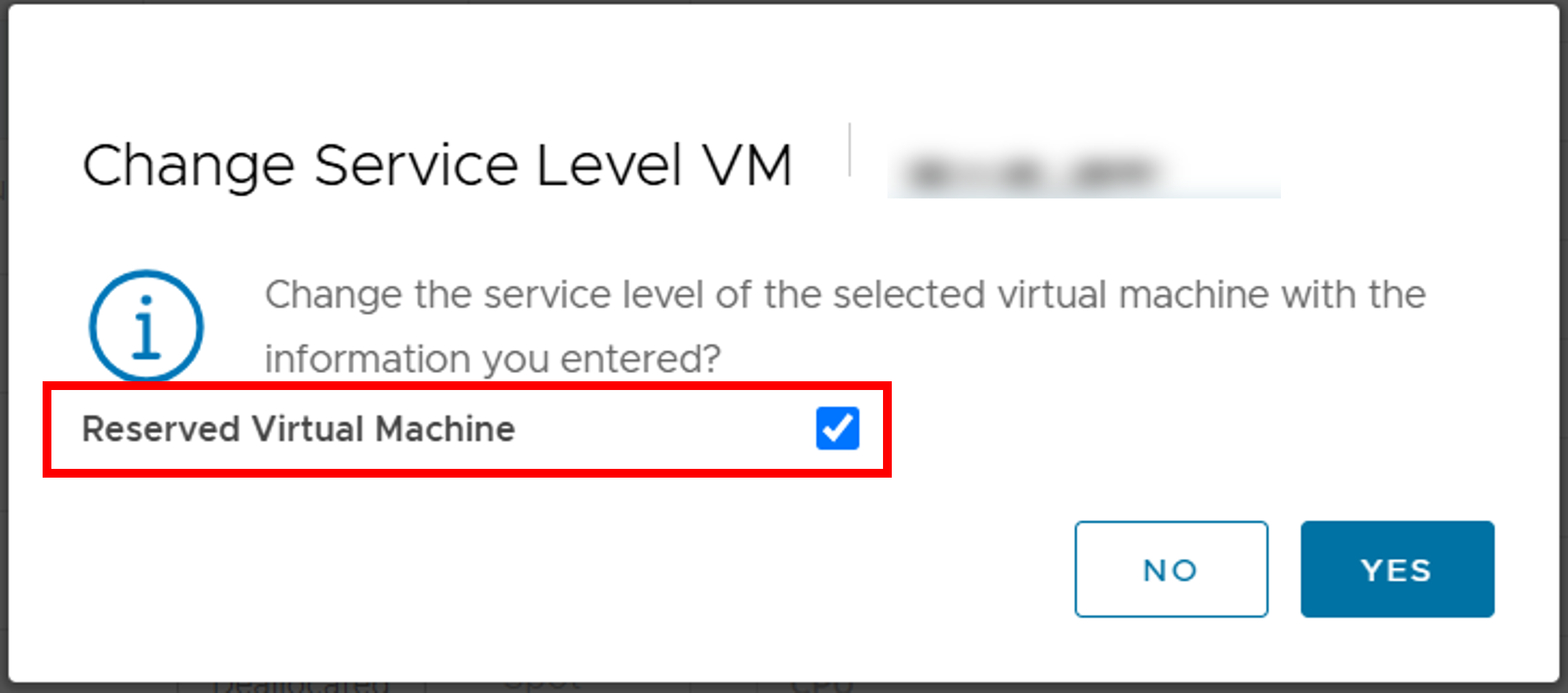
If CPU Pack or GPU Pack are allocated to your project, you can change the service level to “Reserved Virtual Machine” from the “Maintenance” menu.
However, if the virtual machine is subject to forced suspension target (Refer Securing resource and forced deallocation timing ), the service level cannot be changed to “Reserved Virtual Machine.”
8.1.2. Reserved Virtual Machine
Reserved Virtual Machine uses CPU and GPU resources allocated to the project for startup.
The total resources allocated to Reserved Virtual Machine cannot exceed the project’s allocation amount.
The total resources allocated to the project cannot exceed the limit assigned to the institution. However, the total allocation amount for the institution can exceed the overall resources of the system.
An upper limit can be set for the resources available to the Reserved Virtual Machine, and the total amount of allocation for each project must be set below the limit for the entire system (The definition of the resources is discussed below).
You can change to a Spot Virtual Machine even when the Reserved Virtual Machine is in the power-on state.
If there are sufficient available resources when a virtual machine is deployed or power-on, the deployment or reservation of the virtual machine is executed immediately.
If there are insufficient available resources when deploying or power-on a virtual machine, a Spot Virtual Machine in a suspended or operating state is forcibly transited to a deallocated state and executed using available resources.
8.2. How to confirm service level
The service level of a virtual machine can be confirmed on the following screen in the user portal.
8.2.1. Confirmation on dashboard
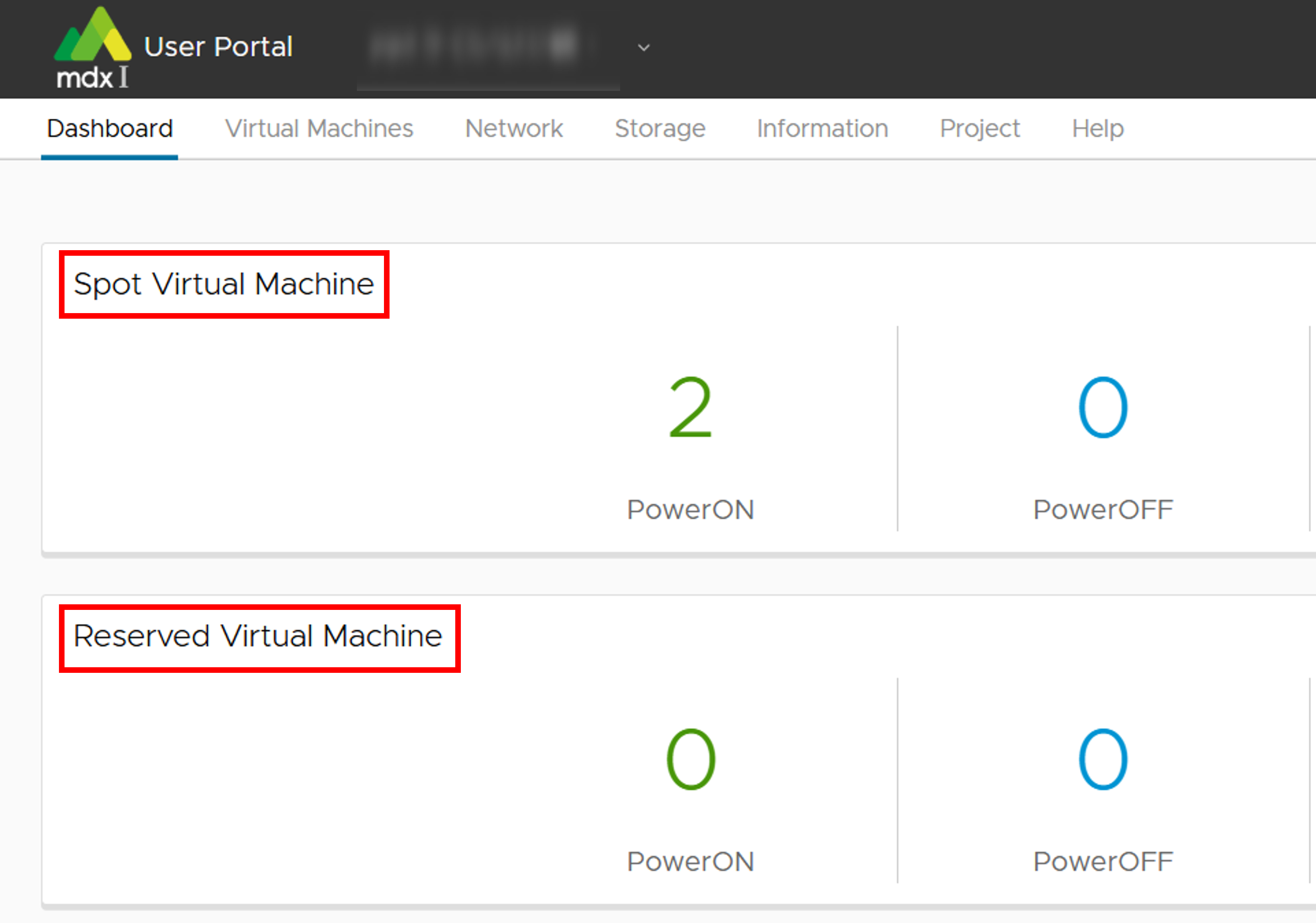
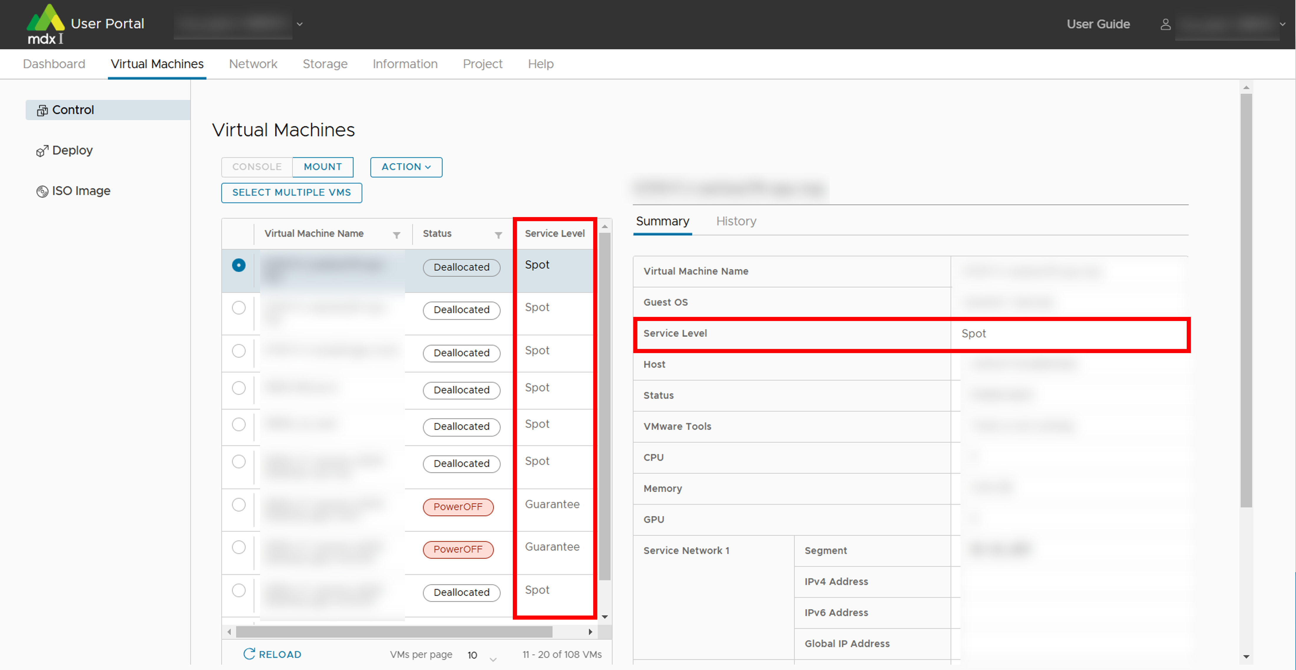
8.2.2. Confirmation in the virtual machine list
8.3. How to specify service level
The service level of the virtual machine can be specified among the following operations in the User Portal.
Deploy of virtual machine
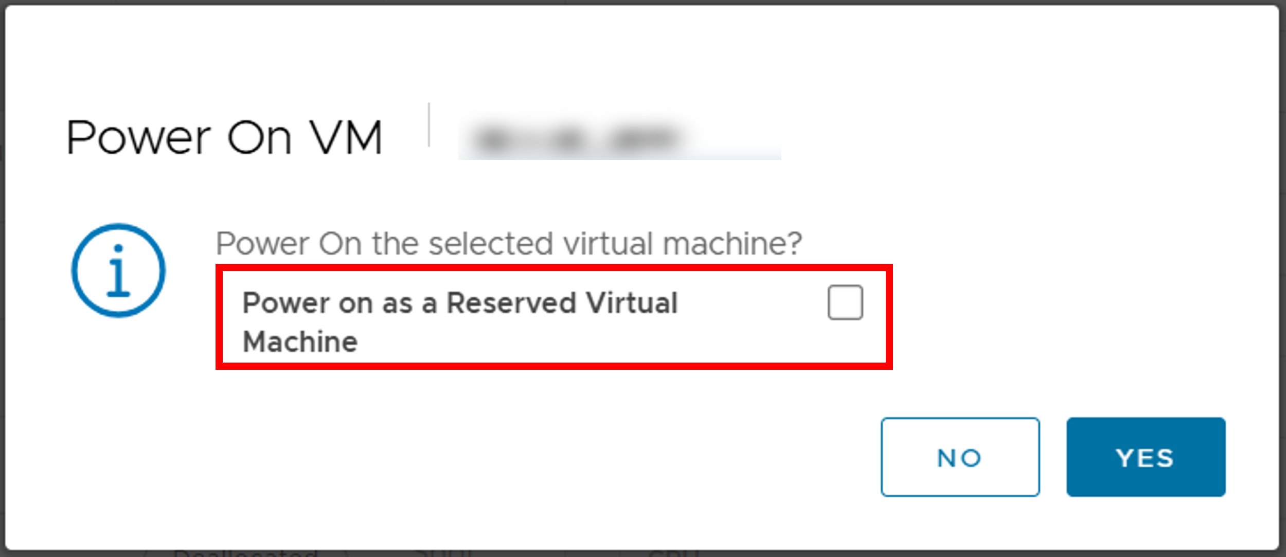
Start a virtual machine
Clone a virtual machine
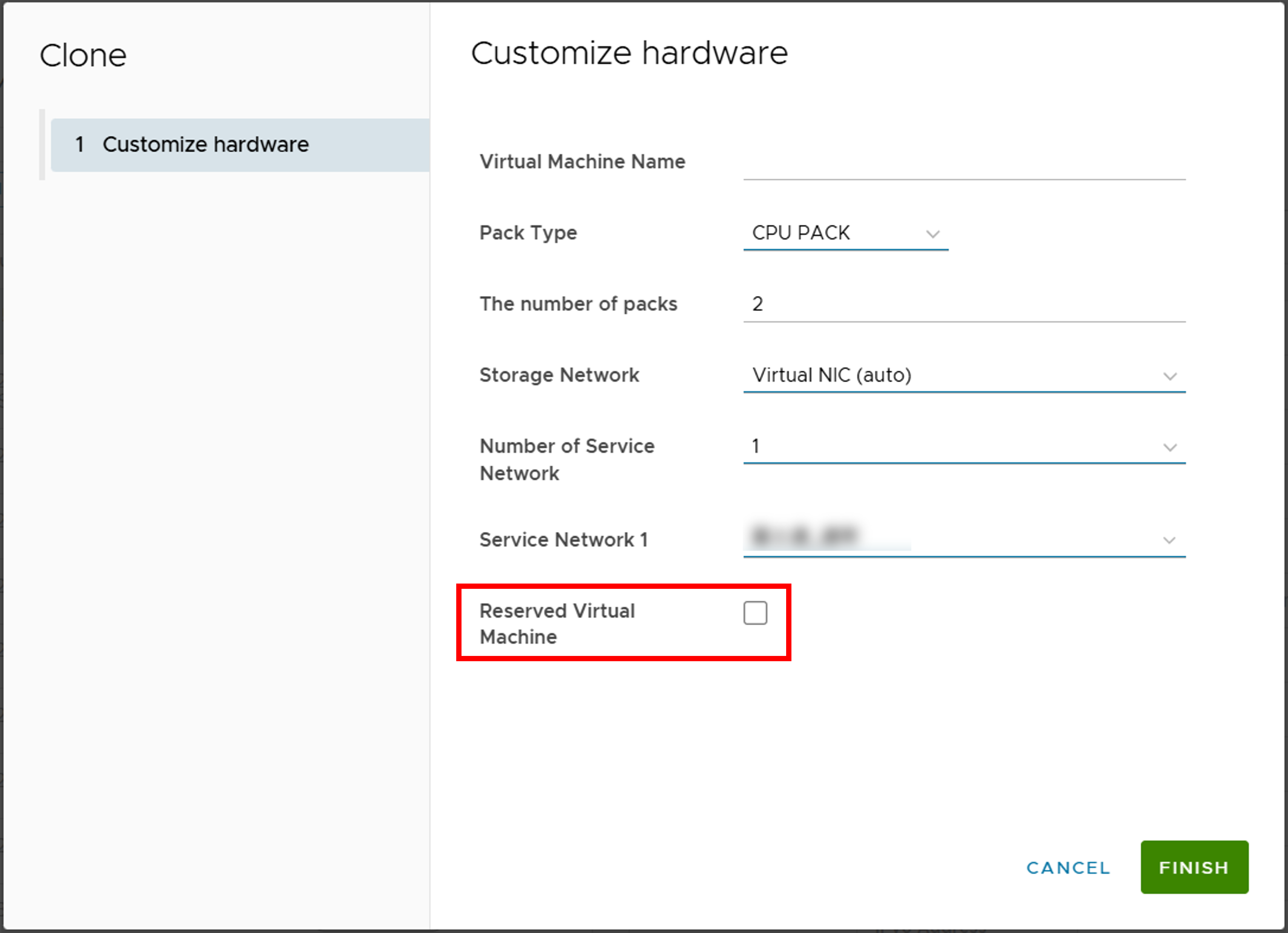
Service level change of virtual machine
8.4. Image for resource use
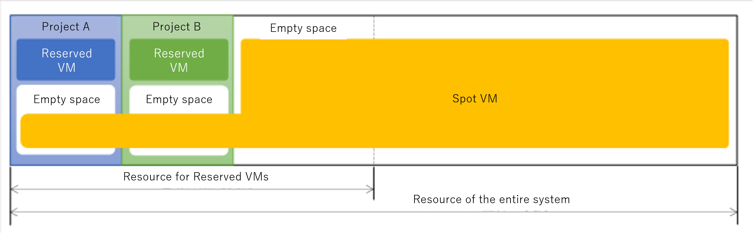
Spot Virtual Machines can utilize resources that are not allocated to the projects for Reserved Virtual Machines.
Even resources allocated to the project can be used for Spot Virtual Machines if they are unused.
The Reserved Virtual Machines cannot use resources beyond those allocated to the project.
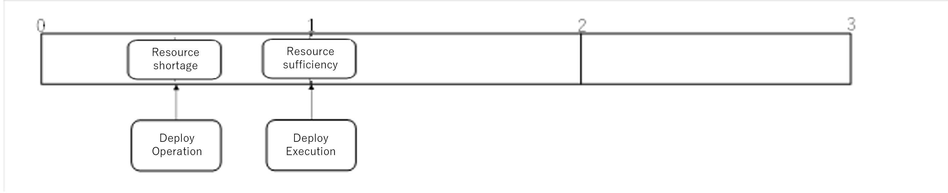
8.4.1. Deployment or startup of Spot Virtual Machines
(Success patarn)
※ “A certain period of time” refers to 24 hours.
Before executing
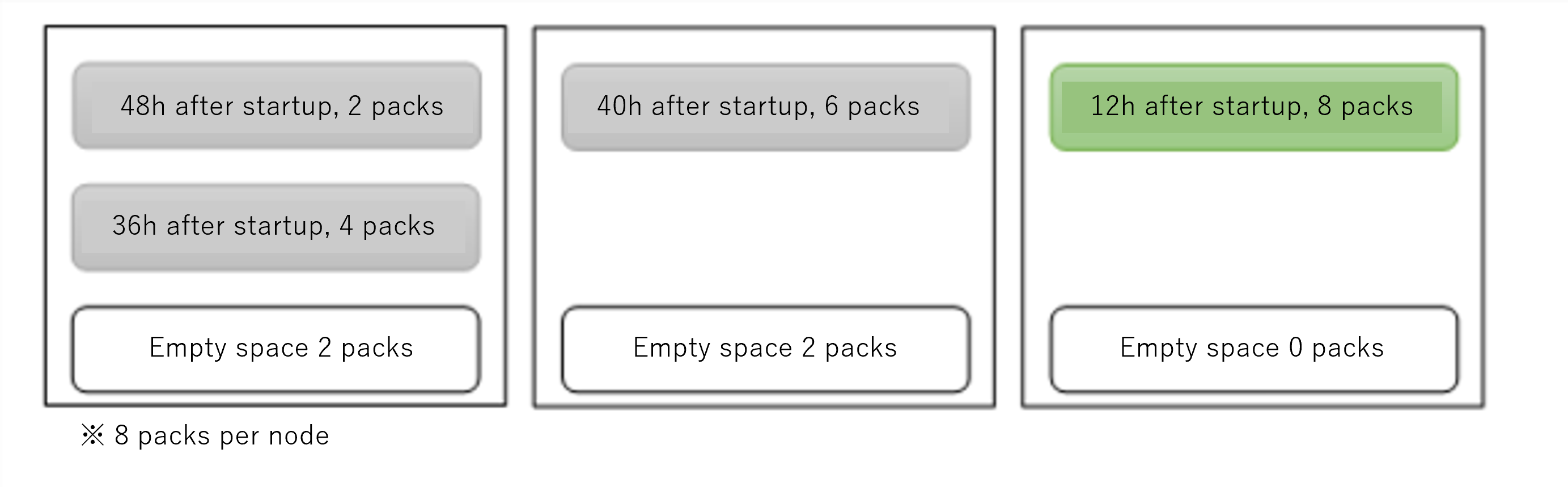
After executing
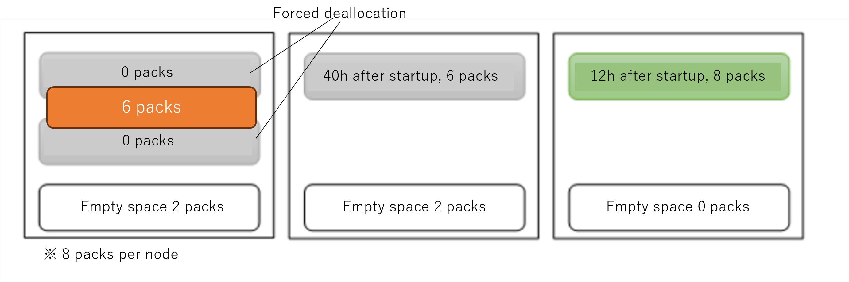
(Failure patarn)

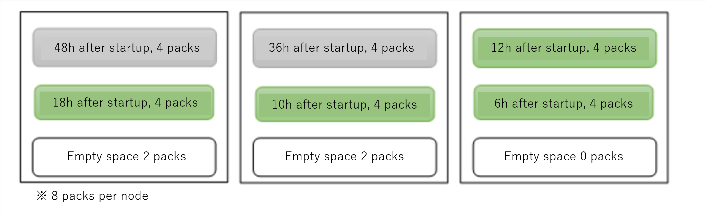
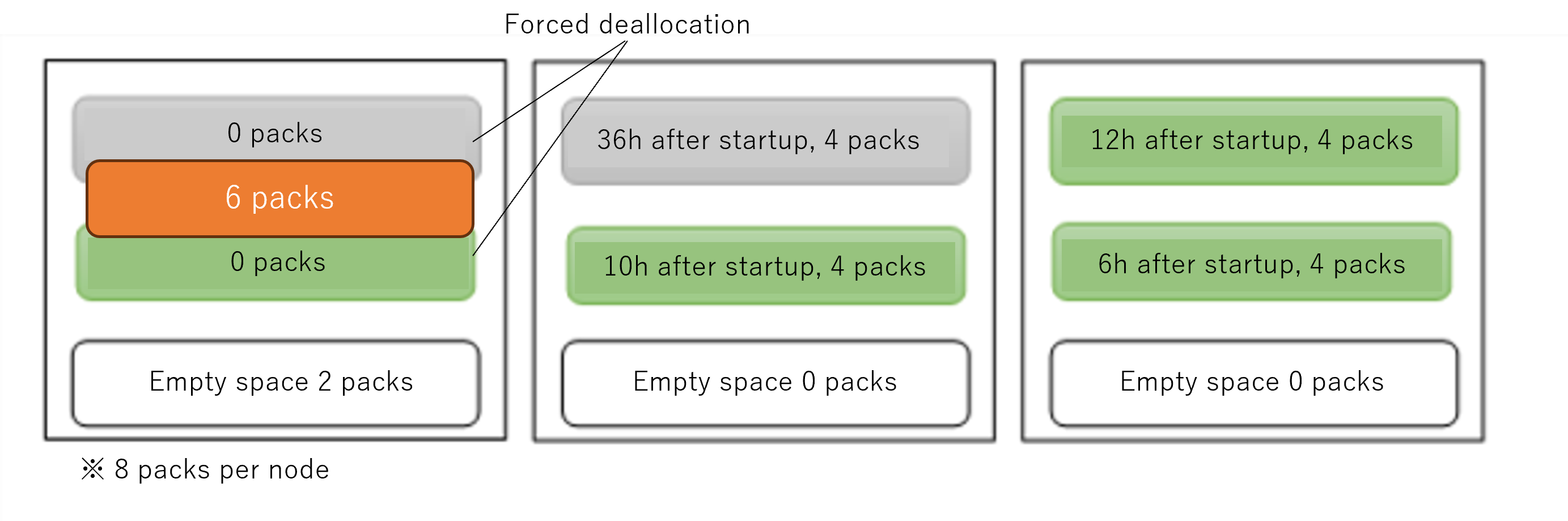
8.4.2. Deployment or startup of Reserved Virtual Machines
8.5. Securing resource and forced deallocation timing
The forced deallocation process of Spot Virtual Machines when the deployment and startup of a virtual machine is performed in the following order at regular intervals.
Insufficient resources are necessary to deploy/start the virtual machine (Deploy/Start is pending)
The timing of the first periodic process after requesting the deployment and startup of the virtual machine
When the necessary resources for the virtual machine can be secured ⇒ Secure the resources and deploy/start the virtual machine.If there are not enough resources for the virtual machine ⇒ The virtual machine that will be the target of forced deallocation is determined and notified in advance.The timing of the further next periodic process
When the necessary resources for the virtual machine can be secured ⇒ Secure resources and deploy/start (Do not forced deallocation of virtual machines scheduled in step 2, and exclude them from forced deallocation target)If there are not enough resources for the virtual machine ⇒ Deallocate the virtual machines targeted for forced deallocation in step 2 to secure resources, and then deploy/start the virtual machine.Image of forced deallocation of virtual machine in step 3.
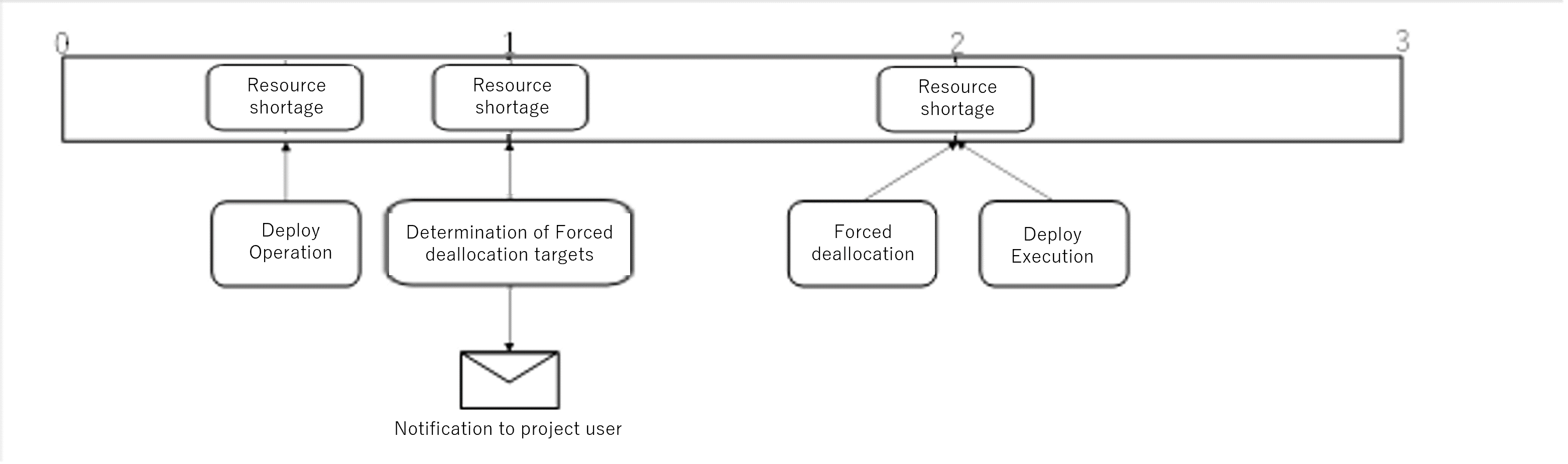
Image of when resources can be secured in step 2.
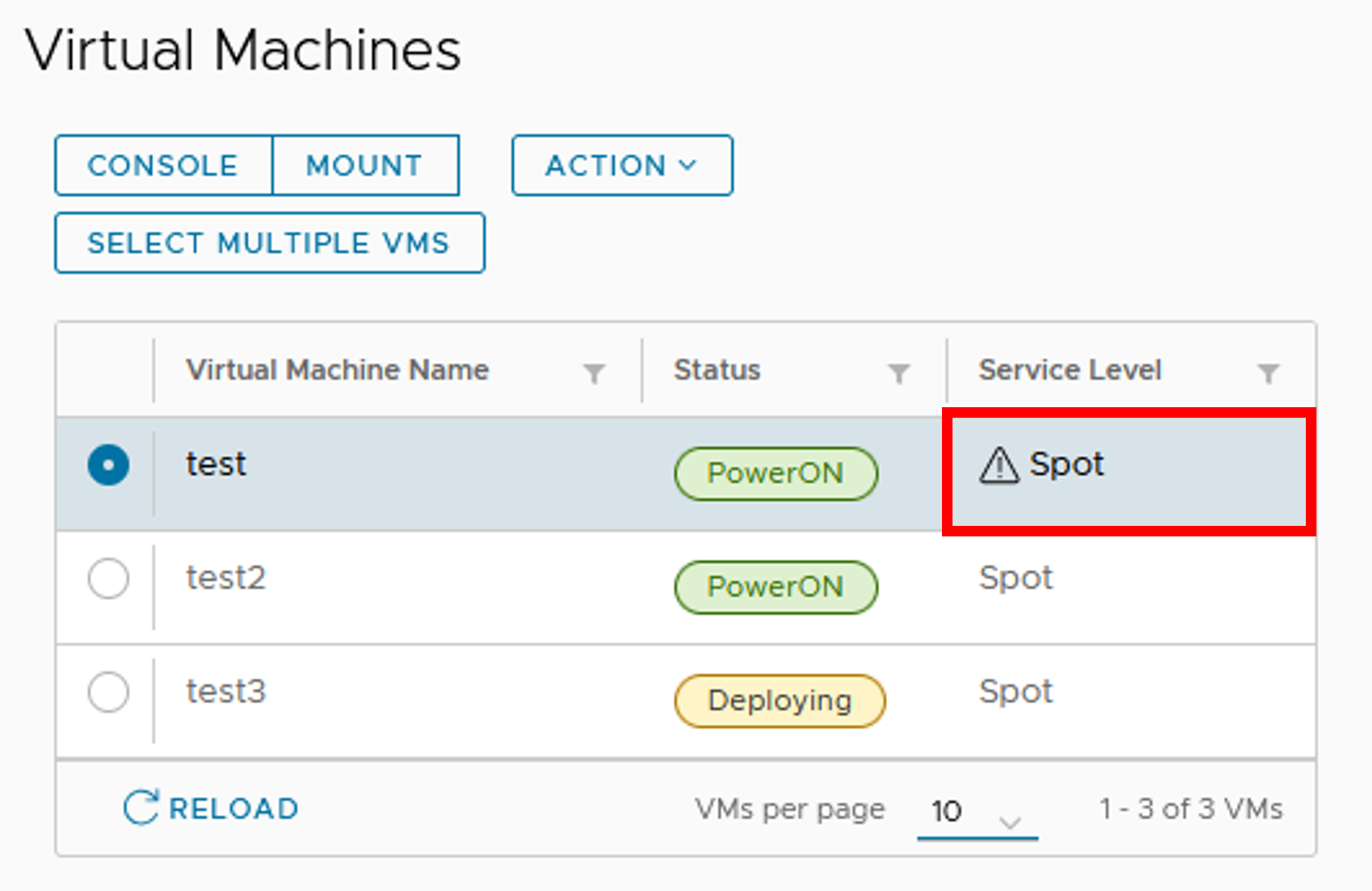
The virtual machines that have been targeted in forced deallocation state can be confirmed on the virtual machine list screen in the User Portal.
A warning mark will be displayed at the beginning of the [Service level] of the target virtual machine.
If it is no longer a forced deallocation target, this warning icon will be removed.
9. Resource reallocation function
This chapter explains the resource reallocation function for the effective use of virtual machine resources.
9.1. Overview of resource reallocation function
The computational resources for Reserved Virtual Machines (Hereinafter referred to as Reserved VM resources) are allocated to the project, and it is possible to create Reserved Virtual Machines within the resources allocated.
The total resources allocated to the project for the Reserved Virtual Machine cannot exceed the upper limit of Reserved VM resources defined by the system.
Whether the requested resources can be secured when the project’s resource application is approved depends on the availability of resources for Reserved Virtual Machines.
If the requested resource is sufficient, the requested resource becomes the allocated resource.
If there are no available resources (Zero), the allocated resource will be zero.
If the requested resource is insufficient, the available resource at that time becomes the allocated resource.
If the total requested resource of each project exceeds the upper limit of Reserved VM resources, the resource reallocation function will increase or decrease the allocated resources.
- Regardless of the above, in a normal project, if the project’s point balance falls below zero and the project is suspended, or if the project has reached its end date,all Reserved VM resources owned by that project will be released (Excluding Node Occupancy Projects).
If a Reserved Virtual Machine was deployed at the time of resource release due to project suspension or end of period, it will automatically be changed to a Spot Virtual Machine.
Each project defines a minimum resource (Rmin).
The total amount of Rmin for each project is controlled so that it does not exceed the upper limit of Reserved VM resources.
The resource reallocation process occurs periodically (On the first of each month).
If there is a change in the allocated resources due to the resources reallocation process, the project user of each project will be notified of the new allocated resources.
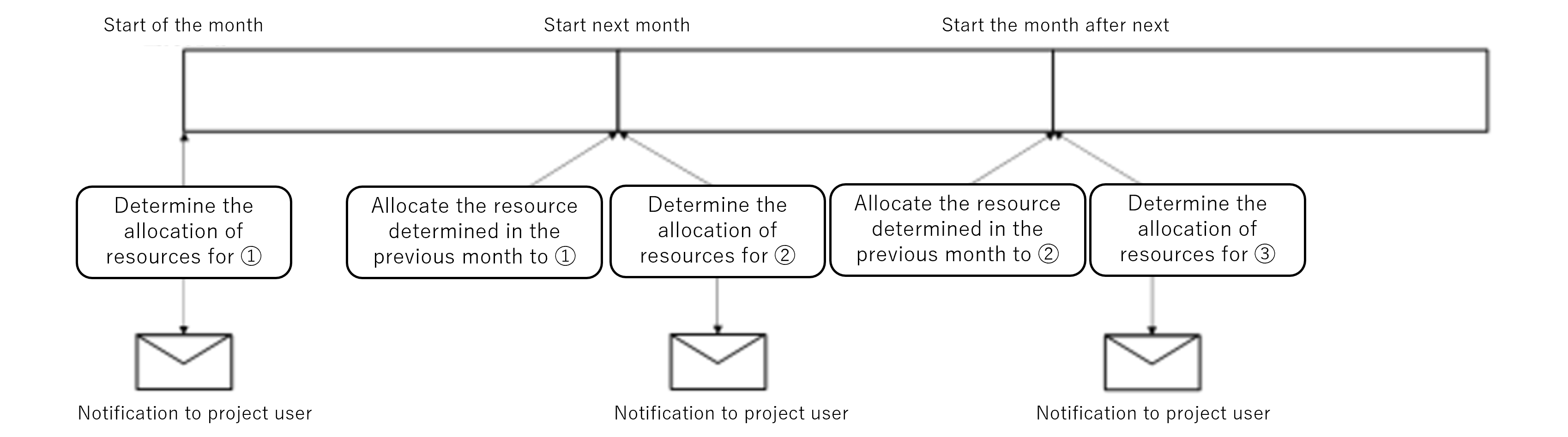
9.2. Timing of resource reallocation
The resource reallocation process occurs on the first day of each month. The resource reallocation event is described below as an example.
9.3. Allocation confirmation
Allocated Reserved VM resources to the project can be found on the dashboard and in the project section.
Dashboard

Project information
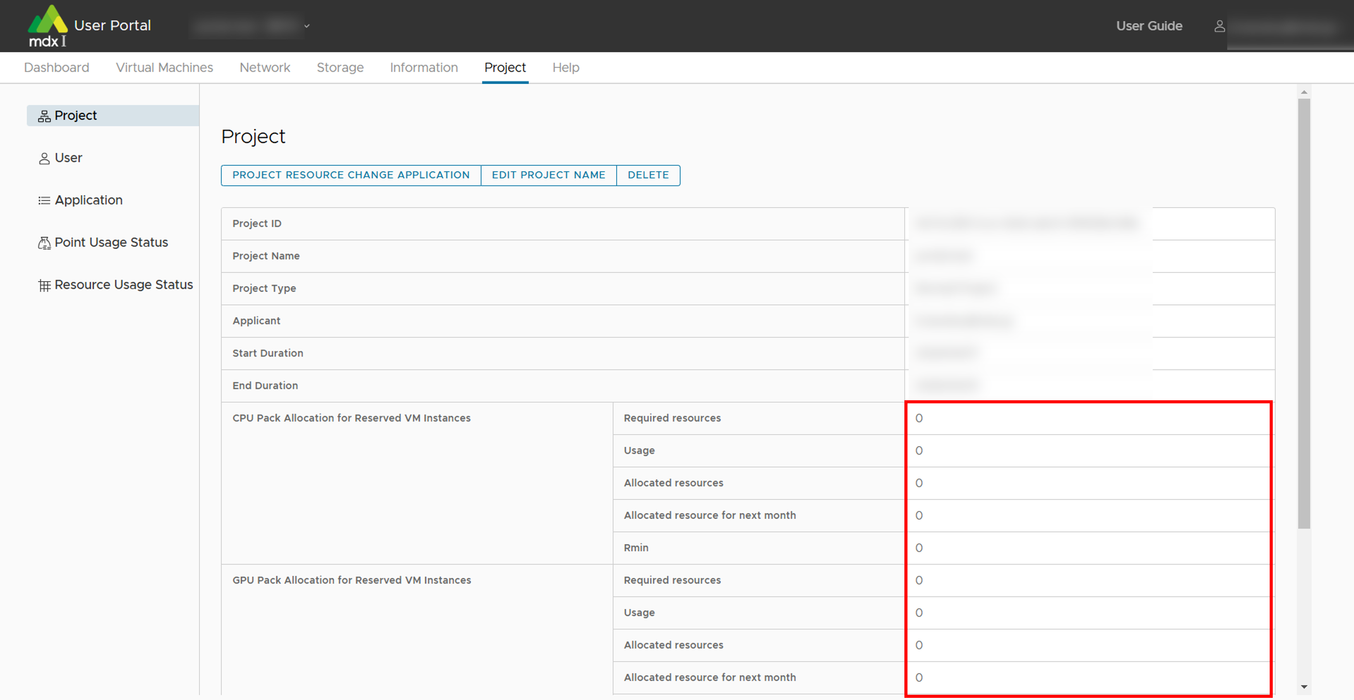
9.4. Description of the item displayed in the project information column
Confirm the allocations in the “Project” section of the user portal, but here is a glossary of terms for each item.
About each item of CPU pack, GPU pack
Item |
Description |
|---|---|
Required resources |
The Reserved VM resources requested by the project |
Usage |
Total resources used by Reserved Virtual Machines in the project (Including power off) |
Allocated resources |
The Reserved VM resources allocated to the project |
Allocated resources for next month |
The Reserved VM resources allocated to the project for the next month, as notified by the resource recovery function at the beginning of each month. |
Rmin |
Lower limit of Reserved VM resources to be allocated to the project |
10. Functional details
10.1. Project application related functions
This section explains how to apply for projects in mdx and other project application-related functions available on the Project Application Portal.
10.1.1. Operation possible for each application status
申請状況/ Application Status |
Operation’s that can be used |
|---|---|
Create new |
Apply, Save |
未申請/ unapplied |
Browse, Apply, Delete |
申請中/ applied |
Browse, Cancel |
却下/ reject |
Browse, Confirm the reason for rejection and re-apply, Delete |
承認済/ approved |
Browse, Copy, Use User Portal |
10.1.2. Project application content details
10.1.2.1. Project ID
This ID is automatically assigned when a project is approved. It is not displayed if the project has not been approved.
10.1.2.2. Project Name
The name of the project to be created. It can be up to 50 characters long and can be entered in Japanese.
10.1.2.3. Project Goal
10.1.2.4. Project Type
Project Type |
Physical node |
Resources that can be used for the project |
Period |
|---|---|---|---|
Normal |
Shared |
Apply after project creation |
Variable (Application) |
Secure (Node occupancy) |
Exclusive |
Apply after project creation |
Variable (Application) |
Trial |
Shared |
Fixed at a certain resource |
3 months |
Please refer to Confirming and changing project information for details on resource applications. Also, the resources in case of selecting Trial are as follows.
Resource name |
Amount of resource |
|---|---|
CPU Pack Allocation for Reserved VM Instances |
8 |
Virtual Disk Storage |
100GB |
High-Speed Storage |
10GB |
Large-Capacity Storage |
10GB |
Global IP Addresses |
1 |
10.1.2.5. Collaborating Institution
Select which agency the project are being applied for is affiliated with. Please note that the project approval process will be handled by the institutional administrator of the affiliated institution.
10.1.2.6. Project Duration
10.1.2.7. Project Applicant Information
Enter the full name, affiliation, address, contactable email address, and phone number of the project applicant.
The first and last name can be entered up to 50 characters.
When applying for a new project, the email address used for email verification will be displayed as the Initial value, but it can be changed as required.
10.1.2.8. Project Representative Information
Enter the full name, affiliation, and contactable email address of the representative.
10.1.2.9. Office Contact Person Information
Please enter the full name, affiliation, and contactable email address of the person in charge of receiving business contacts for the project.
10.1.2.10. Notification
It can be set whether email notifications are issued to project users. The targets are as follows.
Project applicant
Project representative
Office contact person
Project user
Email notifications are issued on the following occasions.
Category |
Notification timing |
|---|---|
Notifications related to project create / resource change applications |
・When the application is made
・When the application is approved or rejected
|
Notifications related to point purchases |
・When the purchase application is made
・When the purchase application is approved or rejected
・When you pay by credit card
・When the application to change payment method is made
・When the application to change the payment method is approved or rejected
・When you cancel the purchase
・When the purchase is cancelled by the administrator
|
Notifications related to use of points |
・When the remaining points fall below 5000
・When the remaining points fall below 0
・When it is one month before the point expiration date
・When the usage of points is suspended by the administrator
・When the suspended usage status is cancelled
|
Notifications related to project usage |
・Whem the notification is updated
・One month before the end of the project duration
・Two weeks before the end of the project duration
・Three days before the end of the project duration
・When 83 days have passed since the remaining point balance fell below 0
(The project will be automatically deleted 90 days after the remaining point balance falls below 0)
|
Notifications related to resource collection |
・1 hour before the Spot Virtual Machine is suspended
・1 month before the collection of resources have been allocated for a Reserved Virtual Machine Instances
|
10.1.2.11. User community
It can be set whether or not to participate in the user community (Slack).
10.1.2.12. Add users who are allowed to purchase points (Optional)
Other than the project applicant users who are allowed to purchase points can also be set. If required to specify multiple people, separate the user IDs with a “Half-width space.”
10.1.2.13. Confirmation regarding country of residence
If one is not a resident of Japan, one needs to provide additional information and report on the following items.
Affiliated institution
Country of affiliated institution
Position
Nationality
Main Place of Residence
10.1.2.14. Questions related to export control
We will confirm whether the applicant has an employment contract with a foreign government, etc., or is receiving economic benefits from a foreign government, etc.
10.1.2.15. Agreement on terms of service and purpose of use
10.1.3. Apply for a new project
Click on [プロジェクトの申請/ Project Application] at the top left of the application list screen.
Enter the required items for the project application.
Items mentioned as [必須/ required] must be entered while applying.
By clicking on [詳細/ detail], you can refer to the explanation for each item.
After completing to enter, if one wants to apply for the project, scroll down the screen and click [申請/ Apply] at the bottom, and to temporarily save the project information, click [保存/ Save].
After returning to the project application list screen, the created project will be displayed as [申請中/ applied] if it is being applied for, and [未申請/ unapplied] if it was temporarily saved. This completes the process of creating a project application.
Note
If one want to temporarily save the project, only the project name is required.
10.1.4. Apply for a temporarily saved project
Apply for a project that is in an unclaimed status.
Click [申請/ Apply] from the Action of the target project on the application list screen.
Modify the information of any item as required.
After completing to modify, if required to apply for the project, scroll down the screen and click [申請/ Apply] at the bottom, and to temporarily save the project information again, click [保存/ Save].
After returning to the project application list screen, the created project will be displayed as [申請中/ applied] if it is being applied for, and [未申請/ unapplied] if it was temporarily saved. This completes the application process.
10.1.5. Delete the contents of project application
Delete the project with an unapplied or rejected status.
Click [削除/ Delete] from the Action of the target project on the application list screen.
If there are no issues with the displayed content, scroll down the screen and click [削除/ Delete] at the bottom.
After returning to the project application list screen, confirm that the project deleted is not displayed. This completes the deletion process.
10.1.6. Withdraw project application
Withdraw the application for a project that is in the application status.
Click [取戻/ Cancel] from the Action of the target project on the application list screen.
If there are no issues with the displayed content, scroll down the screen and click [取戻/ Cancel] at the bottom.
After returning to the project application list screen, confirm that the project for which it is performed the cancellation process is in the [未申請/ unapplied] state. This completes the cancellation process.
10.1.7. Confirm the reason for the rejection of the project and reapply
Click [却下理由を確認し再申請/ Confirm Reject Reason and Reapply] from the Action of the target project on the application list screen.
The reason for the rejection is displayed in red at the top of the screen.
(If required to re-apply)
If it is required to re-apply, modify the information for any item on the current screen according to the reason for rejection.
After completing to modify, if it is required to reapply, scroll down the screen and click [再申請/ Reapply] at the bottom, and if it is required to temporarily save the project information click [保存/ Save].
After returning to the project application list screen, the created project will be displayed as [申請中/ applied] if it is being applied for, and [未申請/ unapplied] if it was temporarily saved. This completes the reapplication process.
10.1.8. Copy the contents of the project application
Apply for or save a new project using the same input information as the approved project.
Click [複写/ Copy] from the Action of the target project on the application list screen.
Modify the information of any item as required.
After completing to modify, if it is required to apply for the project as it is, scroll down the screen and click [申請/ Apply] at the bottom, and to temporarily save the project information, click [保存/ Save].
After returning to the project application list screen, the created project will be displayed as [申請中/ applied] if it is being applied for, and [未申請/ unapplied] if it was temporarily saved. This completes the duplication process.
10.1.9. Move to the user portal to use mdx function
10.1.10. Confirm the contents of the project application
You can check the contents of the project application if the project application is temporarily saved or has been applied at least once.
Click [閲覧/ Browse] from the Action of the target project on the application list screen.
The contents of the target project application will be displayed.
After confirming, scroll down the screen and click on [一覧に戻る/ Return list] at the bottom of the screen to return to the application list screen.
10.2. Point purchase application-related functionalities
For more information on mdx’s point system, please confirm the Usage fee system page .
10.2.1. Confirm the point balance of a project
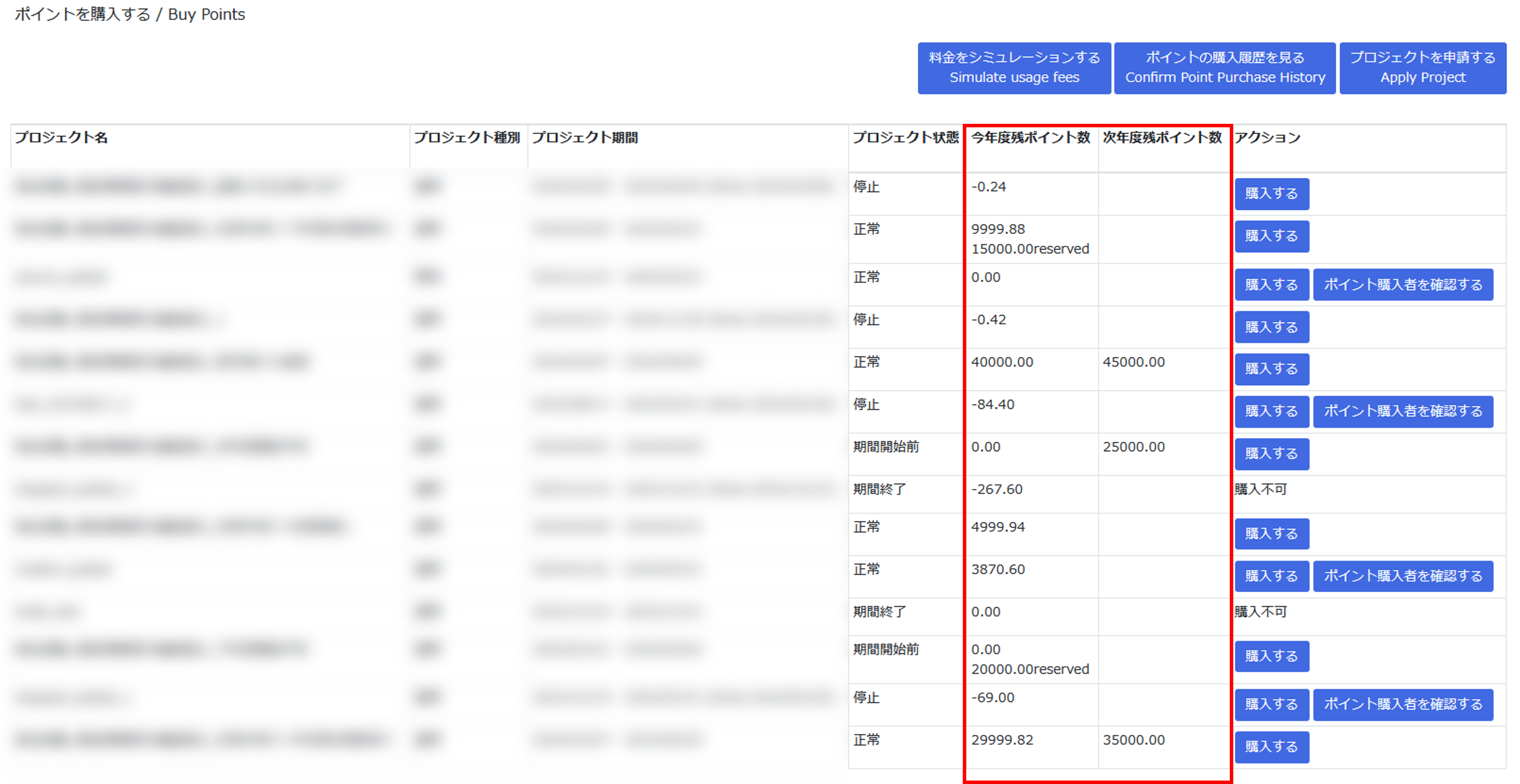
Remaining points for the current fiscal year: Displays the total points available for use in the current fiscal year.
Points indicated as “○○○ reserved” are points that have been reserved but not yet activated, such as before the start of the project duration.
Remaining points for the next fiscal year: Displays the total purchase points available for use in the next fiscal year.
If you want to check the remaining balance in units of points purchased, you can do so from the point usage status in the User portal .
10.2.2. Details of a point purchase application
10.2.2.1. Point Purchaser Information
Enter the point purchaser information. The entry of following items is necessary.
First and Last Name
Institution
Department
Job Title
Email Address
Phone Number
The following information is optional.
Postal code
Address
10.2.2.2. Payment clerks information
If you are entering information for the payment clerks, the entry of following items is necessary.
First and Last Name
Institution
Department
Job Title
Email Address
Phone Number
The following information is optional.
Postal code
Address
10.2.2.3. Request for required number of points
10.2.2.4. Payment method
logged in with GakuNin ID and not affiliated with the university of Tokyo
logged in with mdx Authentication ID
10.2.2.5. Payment Budget
If the point purchaser logs in with GakuNin ID and is affiliated with the university of Tokyo, Choose between two types: “科研費/ KAKENHI (Research FundGrants-in-Aid for Scientific Research)” or “科研費以外/ Non-KAKENHI”.
10.2.2.6. Payment method details
The items that can be set, differ depending on the point purchaser and the payment method.
“logged in with GakuNin ID and not affiliated with the university of Tokyo” or “logged in with mdx Authentication ID”
If you choose to pay by invoice, the items that can be set are as follows.If you have previously purchased points using invoice payment, you can select the previously submitted billing address to apply.Billing Addressee
Billing address
First and Last Name
Institution
Department
Job Title
Postal code
Address
Phone Number
If you choose to pay by credit card, there are no available settings.
“logged in with GakuNin ID and is affiliated with the university of Tokyo”
The items that can be set are as follows.
Budget Manager
Department and Institute
Department code (10 digits)
Project code (12digits) / Budget Category (6digits)
10.2.3. Make a new point purchase application
Make a new point purchase application.
Point purchase in the screen displaying the available projects, click on [購入する/ Purchase] from the actions for the project you want to purchase.
Enter the required fields in the point purchase application.
Fields marked [必須/ required] must be filled in.
For details on the input items of the point purchase application please refer to point purchase application details for more information.
When you have completed the form, click [申請内容を確認する/ Confirm the application] at the bottom left of the application screen.
If there are any incomplete entries, an error message will appear above the application button above the application button.
The names of items that are incomplete will be displayed in red, so please correct them and click [申請内容を確認する/ Confirm the application] again.
Confirm the details of your point purchase request, and if there are no problems, click on [ポイントの購入を申請する / Apply to purchase points].
If you want to temporarily save your input, click [入力内容を一時保存する / Save as draft]. To use a temporarily saved point purchase application, please refer to Restore operation .
If you want to cancel the point purchase application, you can return to the point purchase screen by clicking on [プロジェクト一覧に戻る/ Return project list].
On the point purchase history screen, the status of the applied point purchase application will be displayed as [申請中/ Applied]. This completes the point purchase application process.
10.2.4. Manage users who are allowed to purchase points
10.2.4.1. Add user who can purchase points
The applicant of the project adds a user to permission the point purchase of the project.
On the screen where point purchase possible projects are displayed, click [ポイント購入者を確認する/ Verify purchasers] from the action of the project to be the target.
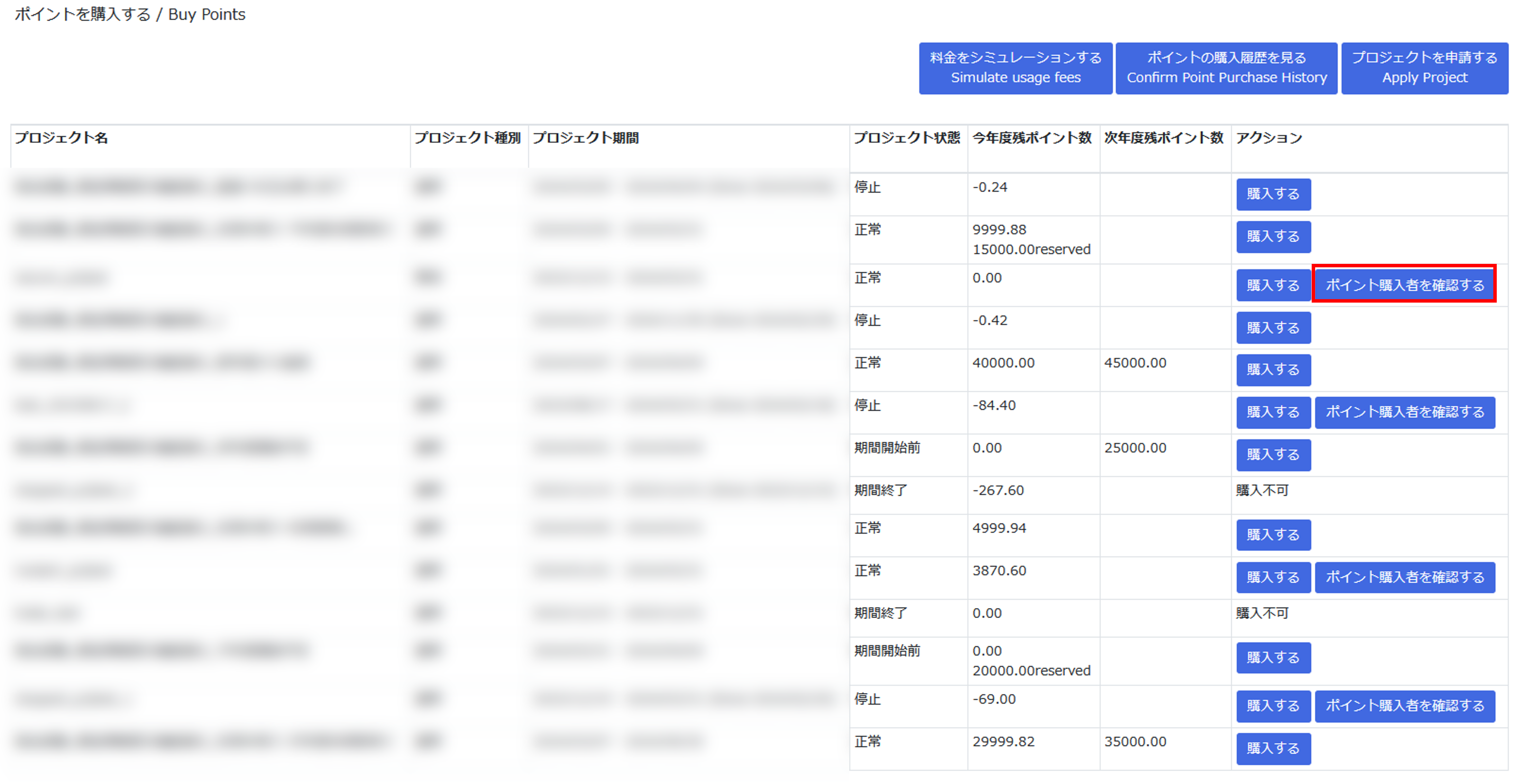
A list of users who are able to purchase points is displayed on the point purchaser list screen.
- Enter the user ID of the user who purchases possible points in the input field at the bottom of the list.When specifying multiple people, please enter a single-byte space with a separation between the user IDs.
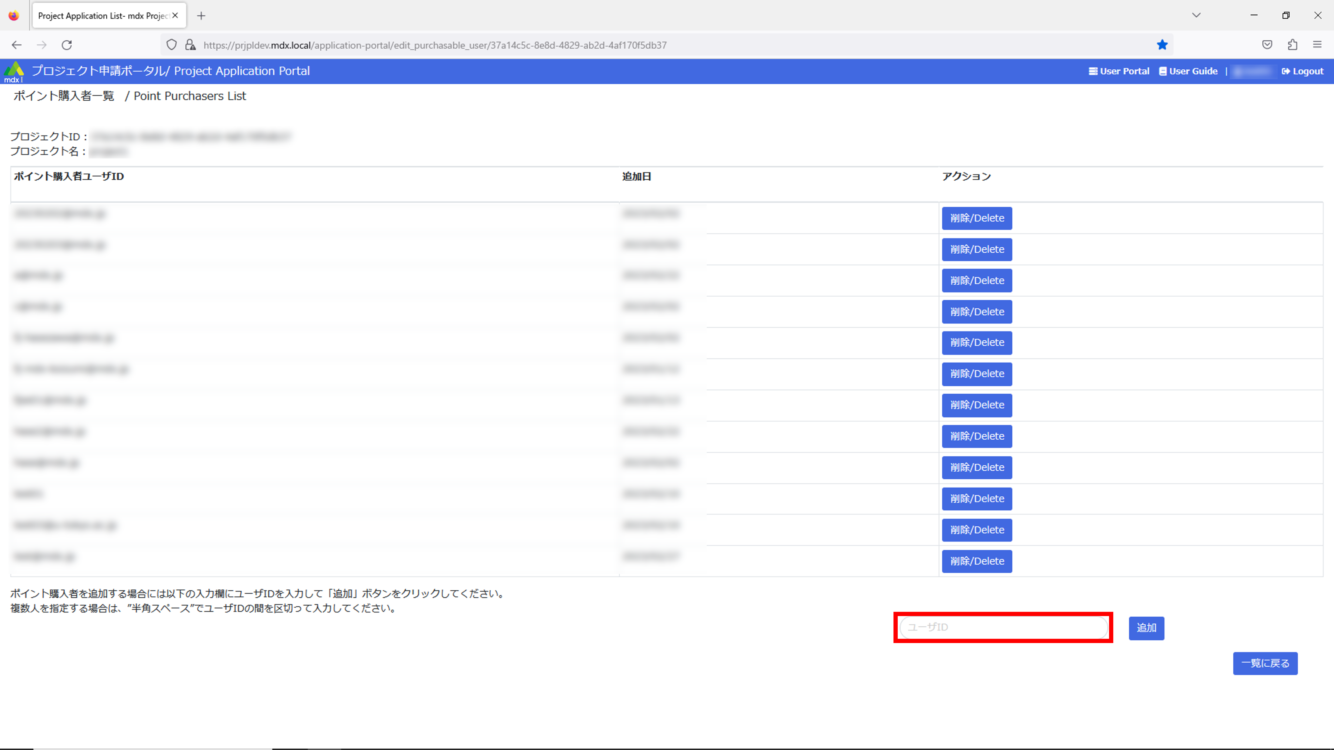
Click [追加/ Add] to the right of the input Field.
Confirm that the list of users who can purchase points has been updated and that the input user has been added. The process of adding users who can purchase points is now complete.
10.2.4.2. Delete user who can purchase points
Move to the point purchaser list screen using the same procedure as when adding.
Click [削除/ Delete] to the right of the user you wish to delete.
Confirm that the list of users who can purchase points has been updated and that the deleted user does not exist in the list. The process of deleting users who can purchase points is now complete.
10.2.5. Restore and apply a temporarily saved point purchase application
Restore and apply for the unapplied point purchase application that was temporarily saved.
On the point purchase history screen, click [申請/ Apply] from the actions of the point purchase application you want to target.
The point purchase application before clicking [入力内容を一時保存する/ Save as draft] will be restored, so enter the necessary information, click [申請内容を確認する/ Confirm the application].
Confirm the details of your point purchase request, and if there are no problems, click on [ポイントの購入を申請する / Apply to purchase points].
On the point purchase history screen, the status of the applied point purchase application will be displayed as [申請中/ Applied]. This completes the process of restoring and applying a temporarily saved point purchase application.
10.2.6. Withdraw point purchase application
Withdraw the point purchase application that is applied.
On the point purchase history screen, click [取消/ Cancel] from the action of the point purchase application you have set as target.
If there is no problem in the displayed content, scroll down the screen and click [ポイント購入を取り消す/ Cancel point purchase] at the bottom.
Return to the point purchase history screen and confirm that the status of the withdrawn point purchase application is displayed as [未申請/ Unapplied]. This completes the withdrawal process.
10.2.7. Reapply for rejected point purchase application
Reapply for rejected point purchase application.
On the point purchase history screen, click [再申請/ Re-apply] from the action of the point purchase application that you want to target.
Check the [却下理由/ Reject reason] in the basic point information at the top of the application screen, and if there is a cause in the point purchase application content, make corrections.
Confirm the details of your point purchase request, and if there are no problems, click on [ポイントの購入を申請する / Apply to purchase points].
On the point purchase history screen, the status of the applied point purchase application will be displayed as [申請中/ Applied]. This completes the process of reapplying for a point purchase application that has been rejected.
10.2.8. Applying a change in payment method for a point purchase application.
On the point purchase history screen, click [支払方法編集/ Edit payment method] from the actions of the targeted point purchase application.
[お支払方法/ Payment method] enter the content you want to change for the following Item.
Click on [編集内容を申請する/ Request edits edits]. This completes the payment method change request process for point purchase applications.
Please note that you will not be able to modify the content of your application on the [支払方法編集/ Edit payment method] screen until the edit payment method application is approved or rejected.
10.2.9. Process payment for point purchase application (Credit card payment only)
Process the payment for point purchase applications that are approved and have credit card as the payment method..
On the point purchase history screen, click [決済情報入力/ Enter payment info] from the target point purchase application action.
Confirm the usage content and if there are no problems, enter the necessary information in the credit card payment application form.
Click [お申し込み内容確認](Confirmation of application details) at the bottom of the input screen.
10.2.10. Withdraw point purchase application
Canceled points cannot be used again and will not be charged.
On the point purchase history screen, click [取消/ Cancel] from the action of the point purchase application you have set as target.
If there is no problem in the displayed content, scroll down the screen and click [ポイント購入を取り消す/ Cancel point purchase] at the bottom.
Return to the point purchase history screen and confirm that the cancelled point purchase request is no longer displayed. This completes the process to cancel a point purchase request.
10.2.11. Duplicate the contents of a point purchase application
Duplicate an approved point purchase application.
On the point purchase history screen, click [複製/ Copy] from the action for the target point purchase application.
The duplicated information for the point purchase application is entered as the initial value for the input item on the [ポイントの購入/ Buy points] screen. This completes the process for duplicating the contents of the point purchase application.
10.2.12. Confirming detailed information about points
Basic point information
Point management number: A unique number automatically assigned when a point purchase request is created.
Approval status: Current status of point purchase application.
Applied: The point purchase application has been submitted and is still pending approval or rejection.
Approved: The point purchase application has been approved.
Rejected: The point purchase application has been rejected. Reject reason can be checked in the point basic information.
Unapplied: It’s temporarily saved state and has not been submitted yet.
Point status: Current status of points.
Valid: Approved and completed payment if the payment method is credit card.
Stopped: Unapproved, or in a state of unpaid after selecting credit card payment. Or the activated points have been temporarily suspended by the administrator.
Canceled: Activated points have been canceled. After cancellation, they cannot be used as points and will not be billed. … Details about cancellation
The following will be displayed only when the “approval status” is “approved”.
Point assignment date: The date the points were approved, or the date the payment was completed if the payment method is credit card.
Point usage start date: The date when the use of points becomes available. It will be a future date if points for the next fiscal year are purchased, etc.
Point expiration date: The last day of the period during which points are available. Points that have expired cannot be used.
Purchase amount of points (tax included): Display the amount charged for purchasing points, including tax.
Billing month: The year and month when the billing is done.
The following is displayed only when the “approval status” is “rejected”.
Reject reason: Display the reason for the purchase request being rejected.
Basic project information
Please check Project application content details for details on each item.
Project Name
Project ID
Collaborating Institution
Project Duration
Applicant Name
Applicant Email Address
Representative Name
Representative Email Address
10.3. Functions related to virtual machine creation
10.3.1. Deploy
Create (Deploy) a new virtual machine from a template.
There are two types of templates: Virtual machine templates that include various preconfigured settings such as OS, and templates without OS settings.
When creating a virtual machine from your own ISO image, please use a template without OS settings.
Deployment procedure are explained below.
Select the template you want to use and click [DEPLOY].
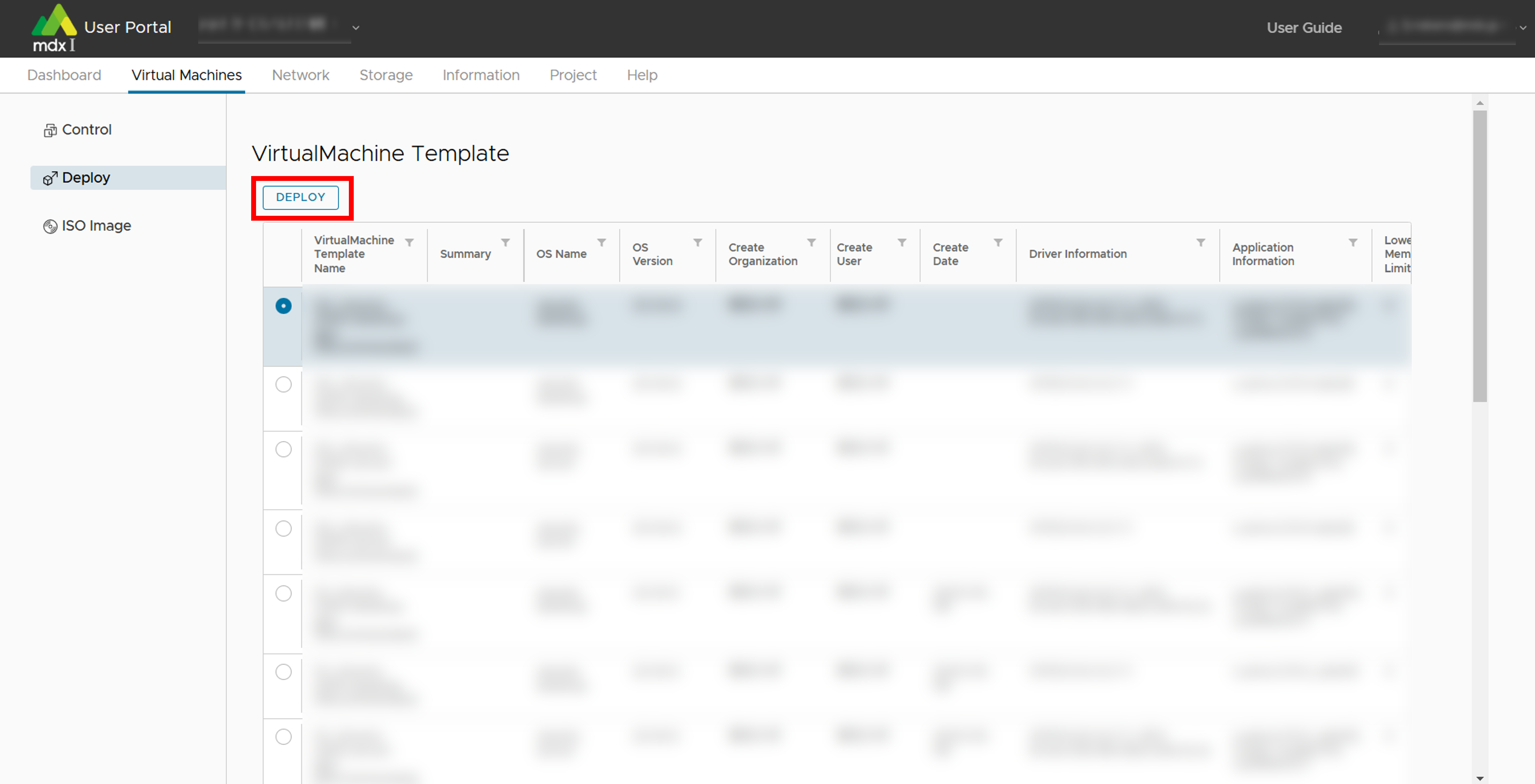
Enter or select each setting item.
For virtual machine templates, only the hardware customization screen is set.
For templates for creating a new virtual machine from an ISO image, additional settings are made on the guest OS selection screen.
<In case of virtual machine template>
<In case of templates without OS settings>
Once you have completed the input, click [Deploy]. This completes the creation of the virtual machine.
10.3.1.1. Setting items during deploy
Hardware customization
Item |
Description |
|---|---|
Virtual Machine Name |
Specify the name of the virtual machine to be created with up to 80 alphanumeric characters.
If you want to deploy multiple virtual machines at the same time, you can write the virtual machine name [(Start number)-(End number)].
The start and end numbers to be specified must be aligned in terms of the number of digits, and if the start number has fewer digits, the upper digits must be filled with “0”.
e.g.) If you specify “machine[0-3]”, 4 machines machine0, machine1,…, machine3 will be deployed with the same customization settings except for the name.
If you specify “machine[00-10]”, 11 virtual machines named machine00, machine01, …, machine10 will be deployed with the same customization settings except for the name.
You can also write multiple virtual machine names separated by commas (,).
e.g.) If you specify “machine0,machine1”, 2 machines machine0, machine1 will be deployed.
These two notations can also be combined.
e.g.) If you specify “machine[0-1],machine2,machine3”, 4 machines machine0, machine1, machine2, machine3 will be deployed.
[Available characters]
・Uppercase letters (A-Z)
・Lowercase letters (a-z)
・Numeric (0-9)
・Symbol:() + -. = ^ _ {} ~
In the case of multiple deployments, the following symbols are also permitted.
・Comma (,) is the delimiter only
・[] is a range specification only
|
Pack Type |
This is only applicable during Normal or Trial Projects. Select [CPU PACK] if the virtual machine to be configured does not use a GPU or select [GPU PACK] if it uses a GPU. |
The number of packs |
This is only applicable during Normal or Trial Projects. Specify the number of CPU packs or GPU packs to be allocated to the virtual machine. ※
However, virtual machines that exceed the capacity of resources (CPU, memory) of a single physical node cannot be configured.
(Maximum of 152 CPU packs and maximum of 8 GPU packs can be specified)
|
CPU |
This is only applicable for Node Occupancy Projects. Specify the number of CPUs to be allocated to the virtual machine (Maximum of 152 can be specified). |
Memory(GB) |
This is only applicable for Node Occupancy Projects. Specify the capacity of memory to be allocated to the virtual machine.
(The maximum physical capacity is 256GB for Generic CPU node and 512GB for GPU Acceleration node,
but when using a GPU or selecting “SR-IOV” for the storage network, the maximum amount of memory that can be specified is reduced because memory reservation is performed).
|
GPU |
This is only applicable for Node Occupancy Projects. Specify the number of GPUs to assign to the virtual machine (Maximum of 8 can be specified). |
Virtual Disk Storage(GB) |
Specify the hard disk space where the OS will be stored. 20 GB or approximately the same amount is required even for minimal install and estimate the capacity by taking into account the space used by applications to be additionally installed. |
Storage Network |
Select the type to be used as the storage network from “Virtual NIC (auto)”, “Virtual NIC (E1000)”, “PVRDMA”, and “SR-IOV”.
When using Lustre, select “Virtual NIC (auto)” or “SR-IOV”, furthermore, select “SR-IOV” when using Lustre with RDMA.
|
Number of Service Network |
Select how many service networks will be connected to the virtual machine to be configured. For a standalone system, 1 is fine. |
Service Network 1, 2, … , n |
Specify the name of the service network to be used. Service networks can be added from the upper menu network segment
(A segment with the same name as the project name is prepared as the project’s default setting).
A number of service network items equal to the number selected in the number of service networks can be displayed/specified.
|
Power On after deploying |
Check this box if you want to reserve the machine immediately after deploying the virtual machine being set up. |
Reserved Virtual Machine |
Only for Normal or Trial projects. Check this box if you want to handle the virtual machine being set up as a Reserved Virtual Machine. |
NVLink |
Checking this item improves processing performance as NVLink is used for communication between GPUs within a node.
However, to use NVLink, the number of GPUs or GPU packs must be set to 8, and the storage network must be set to “SR-IOV”.
|
Login username |
The username under which the public key is set is displayed. |
Public Key |
Specify a public key to login via ssh. |
※Refer to About CPU and GPU Packs for the amount of resources allocated per pack.
Select a Guest OS
Item |
Description |
|---|---|
Guest OS Family |
Select the OS family to be installed in the new virtual machine from Windows/Linux/etc,. |
Guest OS Version |
Select the type/version of OS to be installed in the new virtual machine from the list. |
10.3.2. ISO Image
This screen allows you to upload an ISO image from your local environment for use in creating a virtual machine.
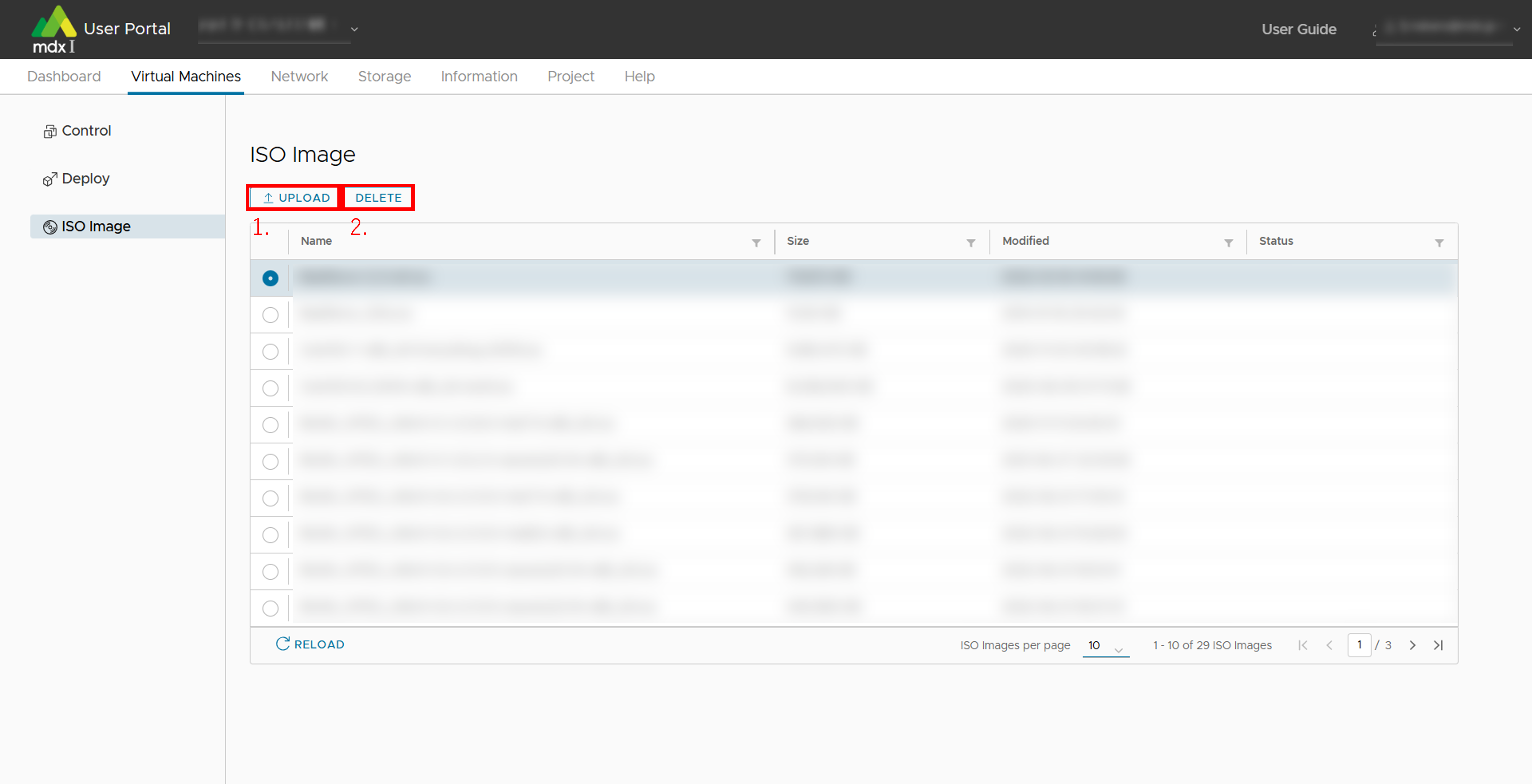
Upload ISO images.
Specify the ISO image of your local environment and click [UPLOAD].
Delete ISO image.

10.4. Functions related to virtual machine control
Status Name |
Description |
|---|---|
PowerON |
The virtual machine is powered ON. |
PowerOFF |
The virtual machine is powered OFF. |
Deploying |
The deployment of the virtual machine is in progress. |
Deallocated |
Hibernate state. The virtual machine is powered off, released computing resources (CPU and GPU). |
Various functions of the control screen can be used for the virtual machines specified in the list.
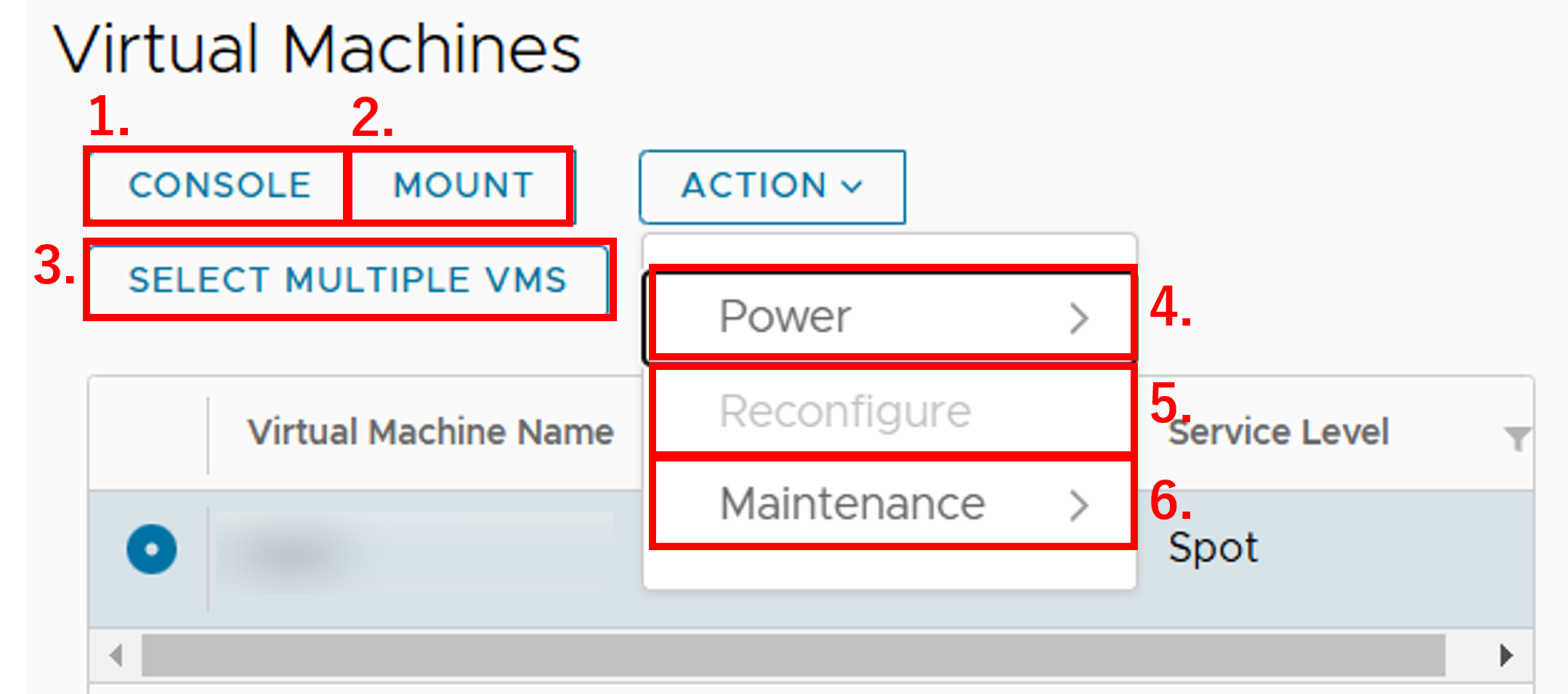
CONSOLE: Checks the status of the virtual machine on the console.
When installing the OS, operations are performed from the console.
MOUNT: Mounts the ISO image on the virtual machine.
The ISO image to be used for mounting should be uploaded to the ISO image upload screen in advance.
SELECT MULTIPLE VMS: Shifts to a mode in which multiple virtual machinesare operated simultaneously (hereinafter referred to as “multiple operation mode”).
When the mode is shifted by clicking [SELECT MULTIPLE VMS], the button name changes to [SELECT SINGLE VM].
Click [SELECT SINGLE VM] to return to the mode of operating a single virtual machine again (hereinafter referred to as single operation mode).
The following functions are available from [ACTION].
Power: Power operation for the virtual machine.
Reconfigure: Change the set value of the virtual machine’s hardware configuration.
Maintenance: Use the maintenance function of the virtual machine.
10.4.1. Operate multiple virtual machines simultaneously
Clicking [SELECT MULTIPLE VMS] switches to multi-operation mode and displays a dedicated screen.
- Check the box to the left of the name of the virtual machine to be operated.To target all virtual machines, check the box to the left of the item name at the top of the list.
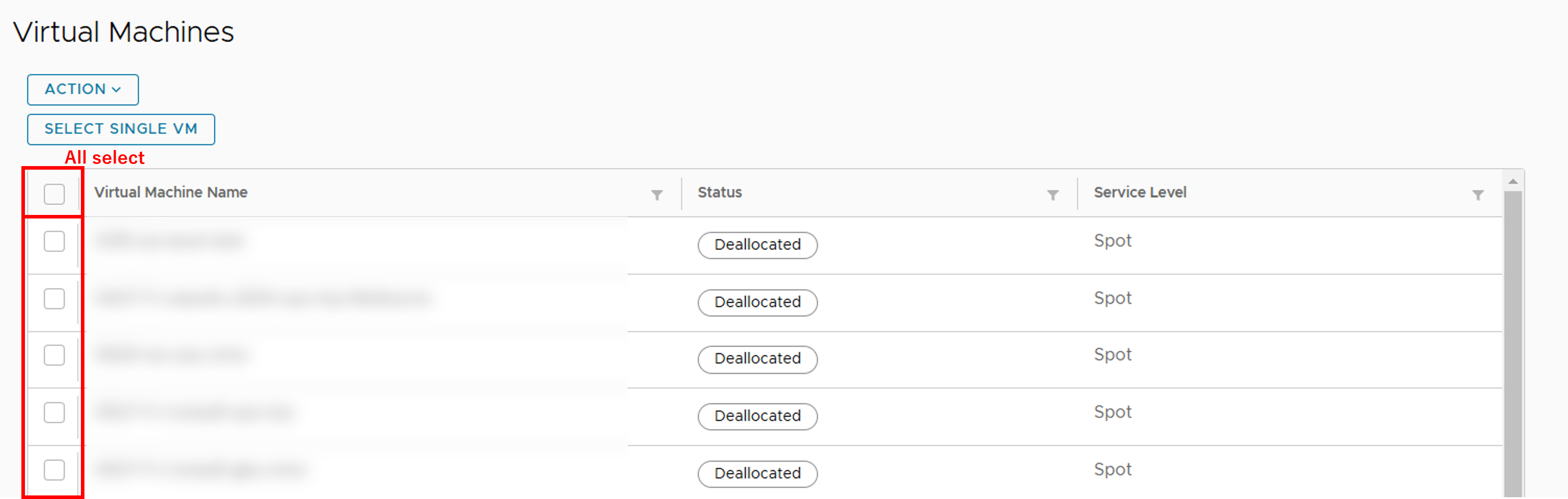
Select an operation for the selected virtual machine from [ACTION].
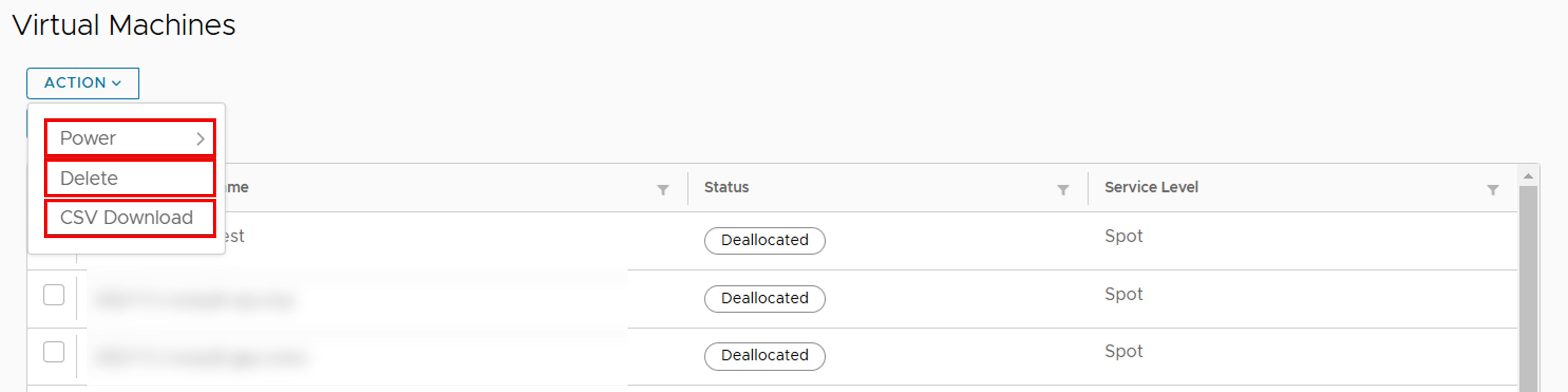
Power: Performs power-related operations on the selected virtual machine.
Possible operations are [Power On], [Shut Down], [Restart], [Reset], and [Power Off](Forced stop).
Delete: Deletes the selected virtual machine.
CSV Download: Outputs information about the network of the selected virtual machine.
10.4.2. Perform power-related operations
10.4.3. Change hardware configuration settings
(For Normal Projects) The number of packs
(For Node Occupancy Projects) CPU
(For Node Occupancy Projects) Memory(GB)
(For Node Occupancy Projects) GPU
Number of Service Network
Service Network
Virtual Disk Storage
Add and delete virtual disks
Use of NVLink
10.4.4. Maintenance
You can perform other operations from [ACTION] > [Maintenance].
Rename: Change the name of the virtual machine. Details of available characters can be found at Configurations for deployment .
Delete: Delete the virtual machine.
Clone: Clone the virtual machine.
Deallocate: Deallocate the virtual machine (Change Status to “Deallocated”) to free up computing resources allocated to the virtual machine.
The status of the virtual machine after hibernation depends on the installation status of the VMWare Tools .
The status of VMWare Tools can be checked under the item [VMWare Tools] in the summary tab displayed in the virtual machine’s detailed information.
Virtual machine with VMware Tools installed and running: Shut Down → CPU and GPU deallocation
Virtual machine where VMware Tools is not installed or installed but not running: Power Off → CPU and GPU deallocation
Change Service Level: Changes the service level of the current virtual machine. Change from “Spot” to “Guarantee” or from “Guarantee” to “Spot”.
Cancel Allocation: If a virtual machine is in the process of booting and waiting for resources to become free, cancels the booting process.
Import OVF: Imports an OVF image of a virtual machine.
Export OVF Template: Export an OVF image of a virtual machine.
ACL Settings: Add ACL settings based on the IP address of the specified machine. For details refer to ACL settings .
DNAT Settings: Add DNAT settings based on the IP address of the specified machine. See DNAT settings for details.
10.4.4.1. Use “Clone” to replicate virtual machines
If you want to clone a virtual machine, go to [ACTION] > [Maintenance] > [Clone].
The settings you can specify for cloning are the same as the deployment settings. You can also clone multiple virtual machines by specifying the virtual machine name in a specific format.
Details can be found at Configurations for deployment .
10.4.4.2. Create a virtual machine using an OVF image.
Export
Note
When performing this operation, please confirm that the status column indicating the virtual machine status is “Deallocated”.
Check the virtual machines to be exported from the list on the Control screen.
Click [ACTION] > [Maintenance] and click [Export OVF Template].
Click [YES] on the confirmation screen.
Save two .ovf and .vmdk files locally using the browser’s download function.
Import
Click [ACTION] > [Maintenance] and click [Import OVF].
Click on the .ovf and .vmdk files generated during export in the local files.
Enter other items. Details can be found at Configurations for deployment .
Click [YES] when you are finished.
10.5. Network setting
10.5.1. Segment
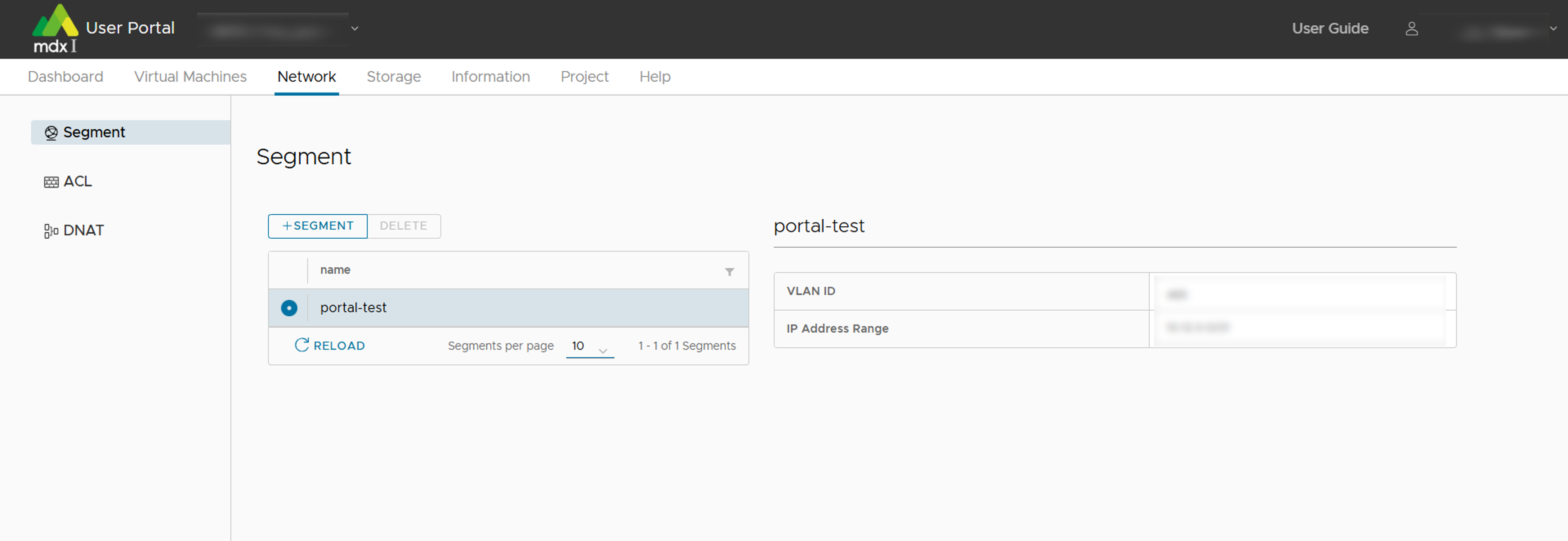
By selecting any segment from the list, you can confirm the parameters of the segment.
VLAN ID
IP Address Range
10.5.1.1. Add segment
Add a new segment.
Click [+SEGMENT] at the top of the main screen/list.
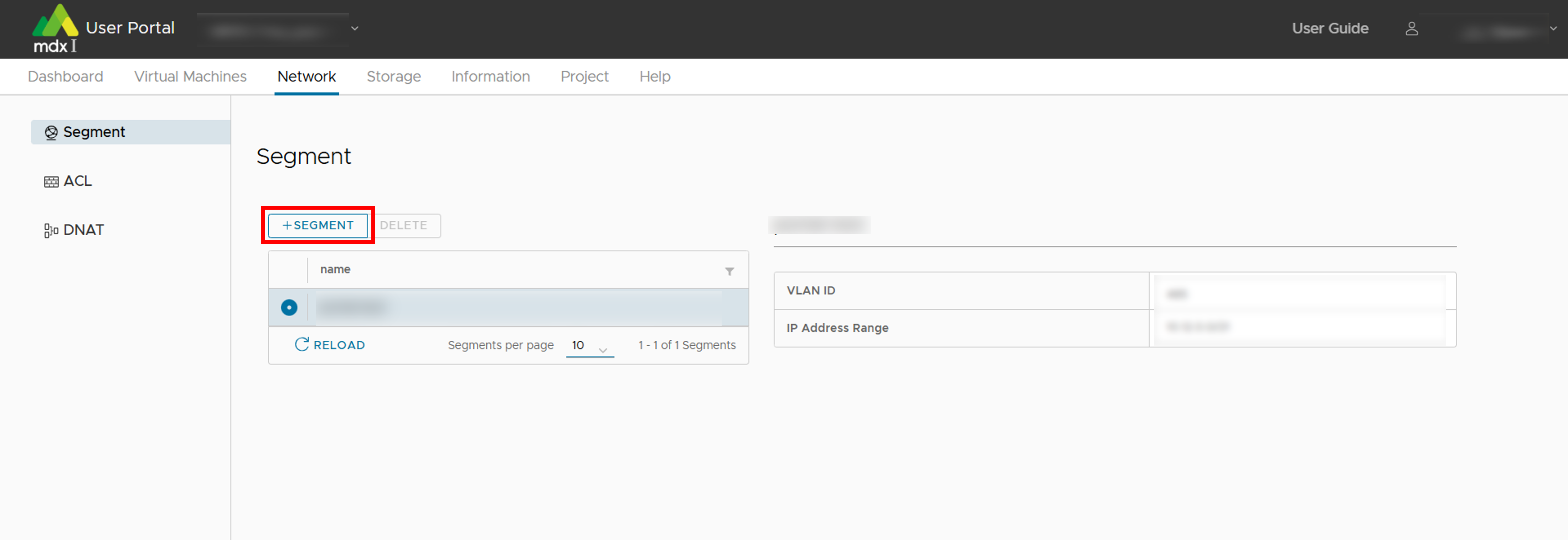
Enter a name for the new segment.

Click [ADD].
10.5.1.2. Segment deletion
Delete unused segments.
Select optional segment.
Click [DELETE] at the top of the main screen/list.
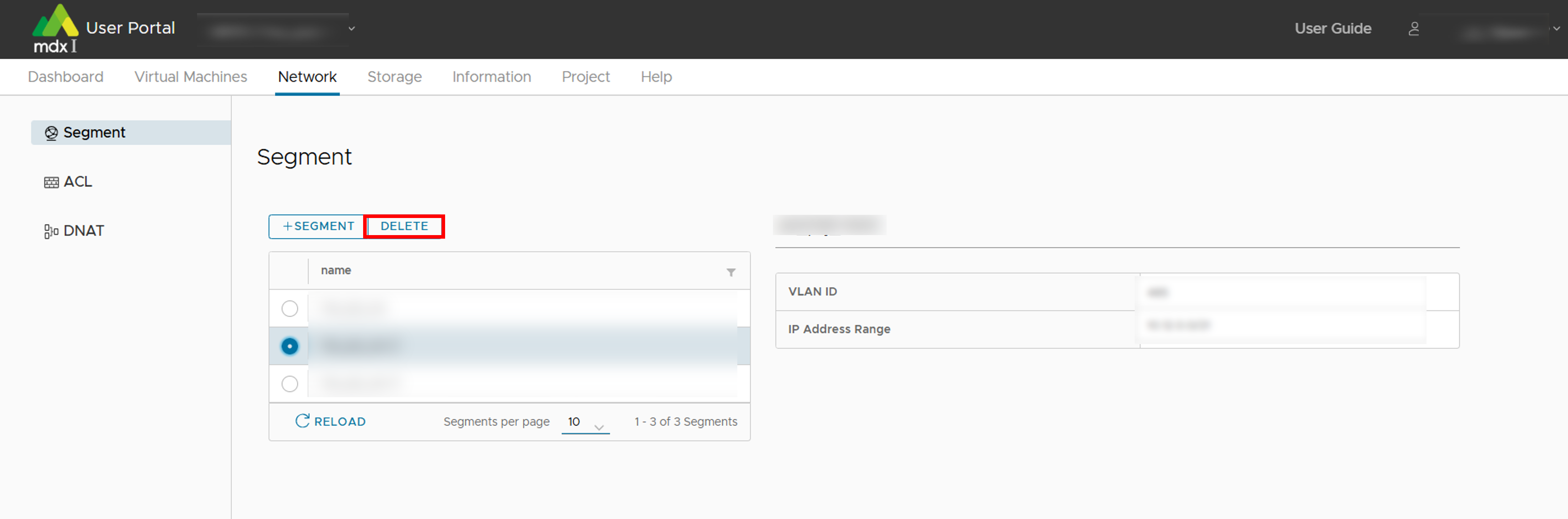
If it is ok to delete, click [YES].
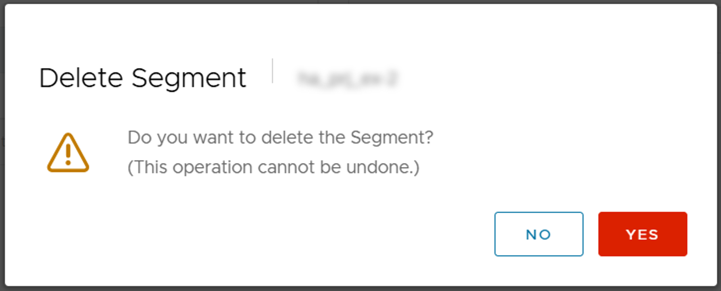
10.5.2. ACL(Access Control List)
Note
Select any segment for ACL settings from the list at the top of the main screen.
Click on the tab from the list at the bottom of the main screen for either IPv4 or IPv6, whichever network settings you want to confirm.

10.5.2.1. Setting items
Item |
Description |
|---|---|
Protocol |
Select the protocol to allow from ICMP (ICMPv6 for IPv6), TCP, or UDP. |
Src Address / Src Prefix Length |
Specify the source IP address to allow access.
The prefix length determines the address range. Only the address specified here is allowed to connect.
|
Src Port |
Specify the source port number to which access is allowed. Specifying multiple port numbers
(Example: “80,443”), a range of port numbers (Example: “22-443”), or Any (All) can be specified.
|
Dst Address / Dst Prefix Length |
Specify the IP address of the virtual machine to be allowed access.
The prefix length determines the address range. Only the address specified here is allowed to connect.
|
Dst Port |
Specify the port number of the virtual machine to allow access. For details on how to set the port number and network address,
(Example: “80,443”), a range of port numbers (Example: “22-443”), or Any (All) can be specified.
|
Tips
please confirm the FAQ on DNAT and ACL settings About DNAT/ACL of FAQ .
10.5.2.2. Setting method of ACL
Click [+RECORD].
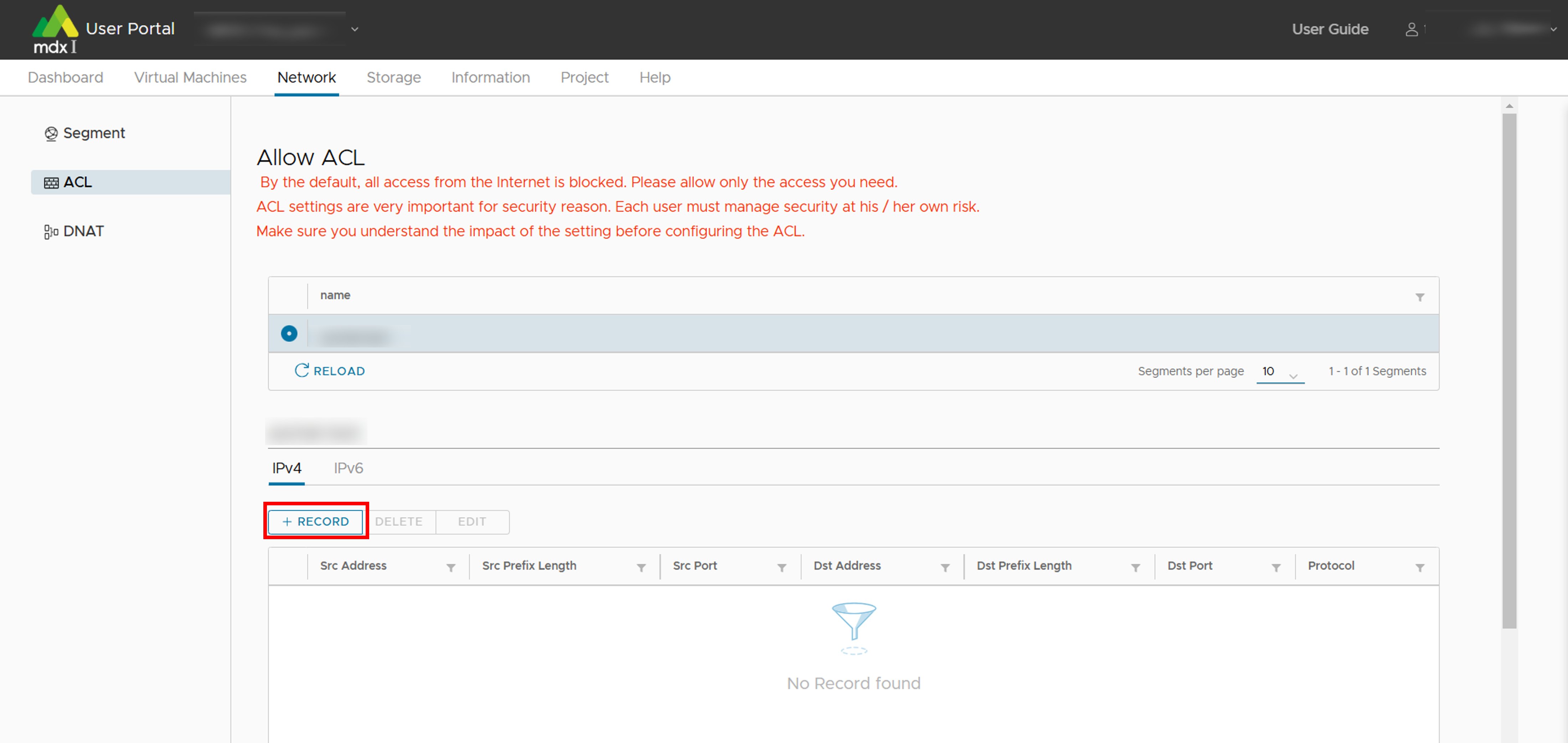
Enter each setting item.
Click [ADD] when you are finished.
10.5.2.3. Record deletion
Select any record you want to delete and click [DELETE].
A confirmation screen will be displayed, so if there are no issues, click [YES].
10.5.2.4. Edit record
Select any record you want to change and click [EDIT].
Update the setting item you want to change.
Click [EDIT] when you are completed.
10.5.3. DNAT
Note
The setting items in DNAT are as follows.
Item |
Description |
|---|---|
Src global IPv4 address |
Specify the global address of the conversion destination. |
Segment |
Specify the segment to be targeted. |
Dst private IP address |
Specify the IP address of the virtual machine to be converted. |
The DNAT setup procedure is explained below.
10.5.3.1. Adding DNAT settings
Click [+DNAT].
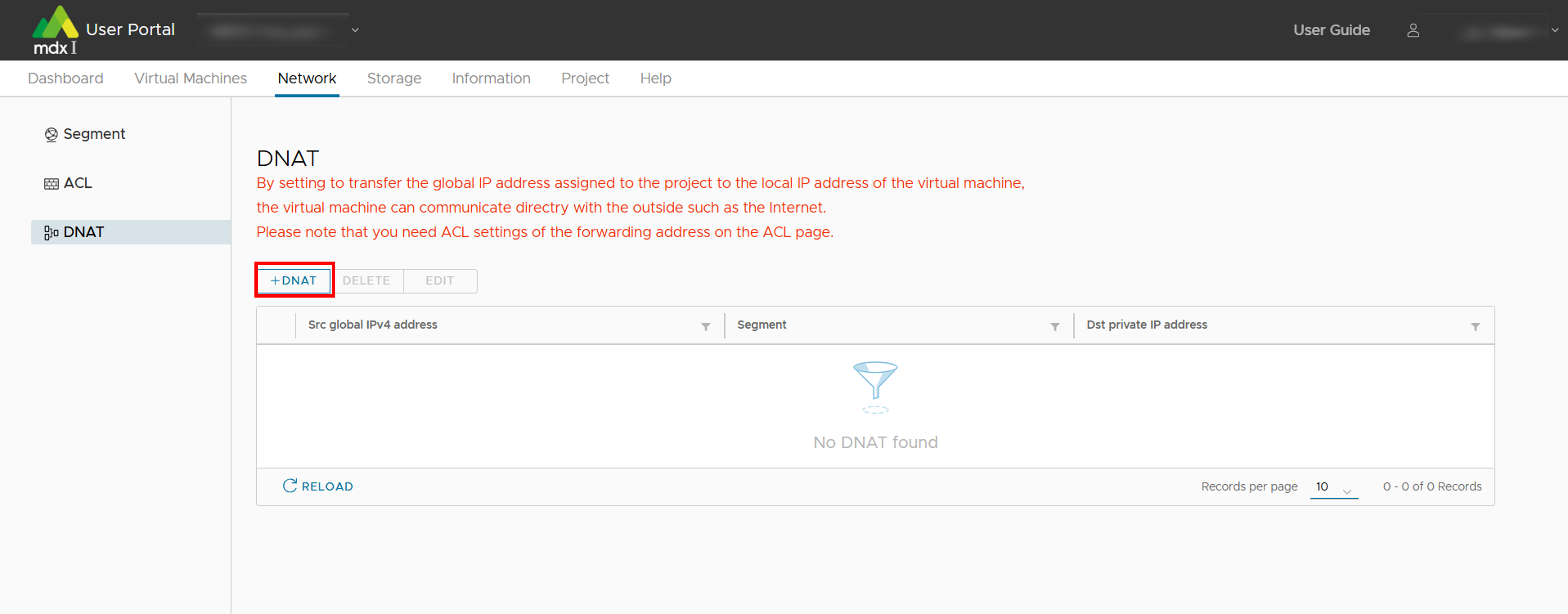
Enter each setting item.
Click [ADD] when you are finished.
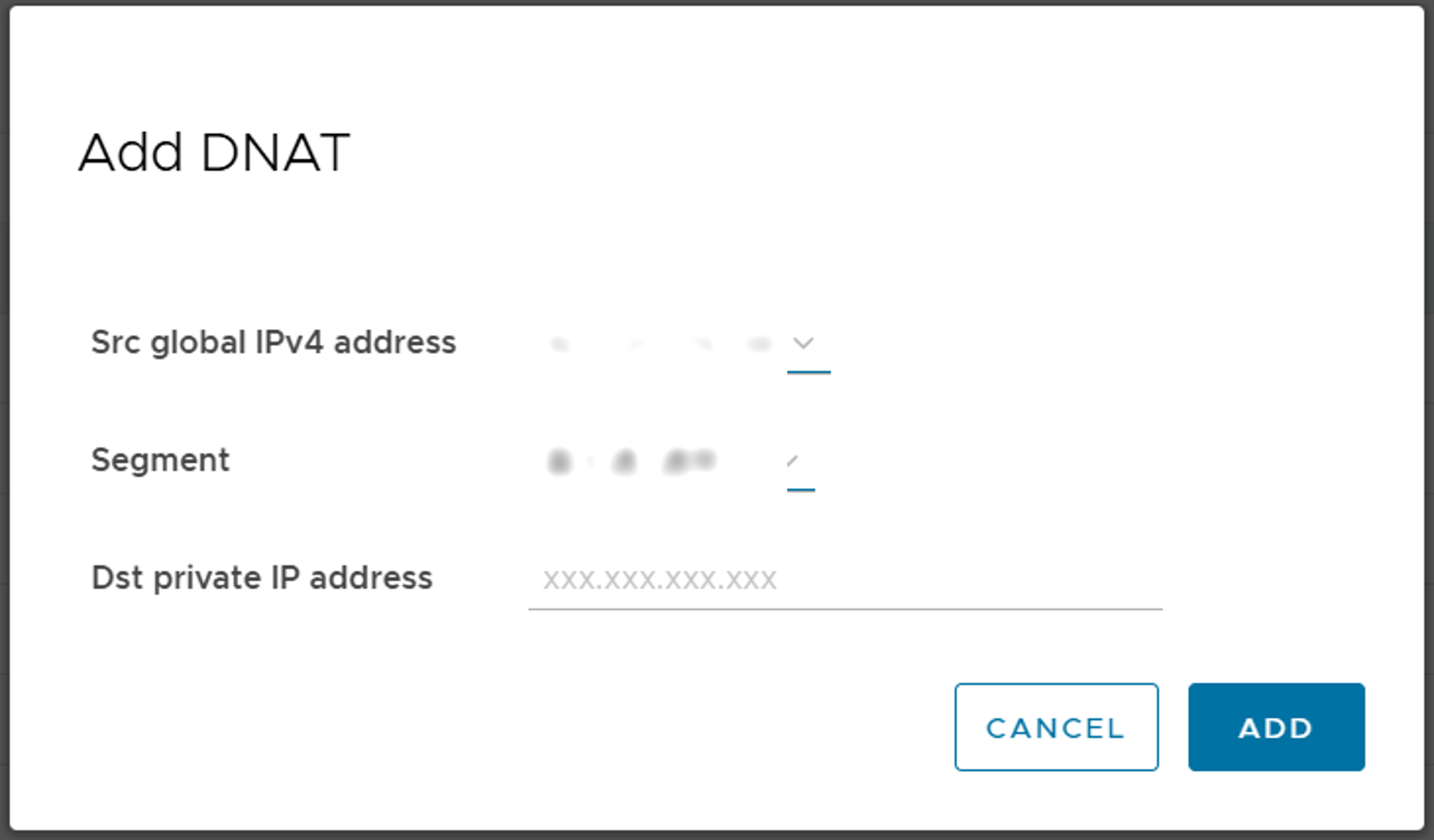
10.5.3.2. Deletion of DNAT settings
Click on [DELETE] with any DNAT setting selected for deletion.
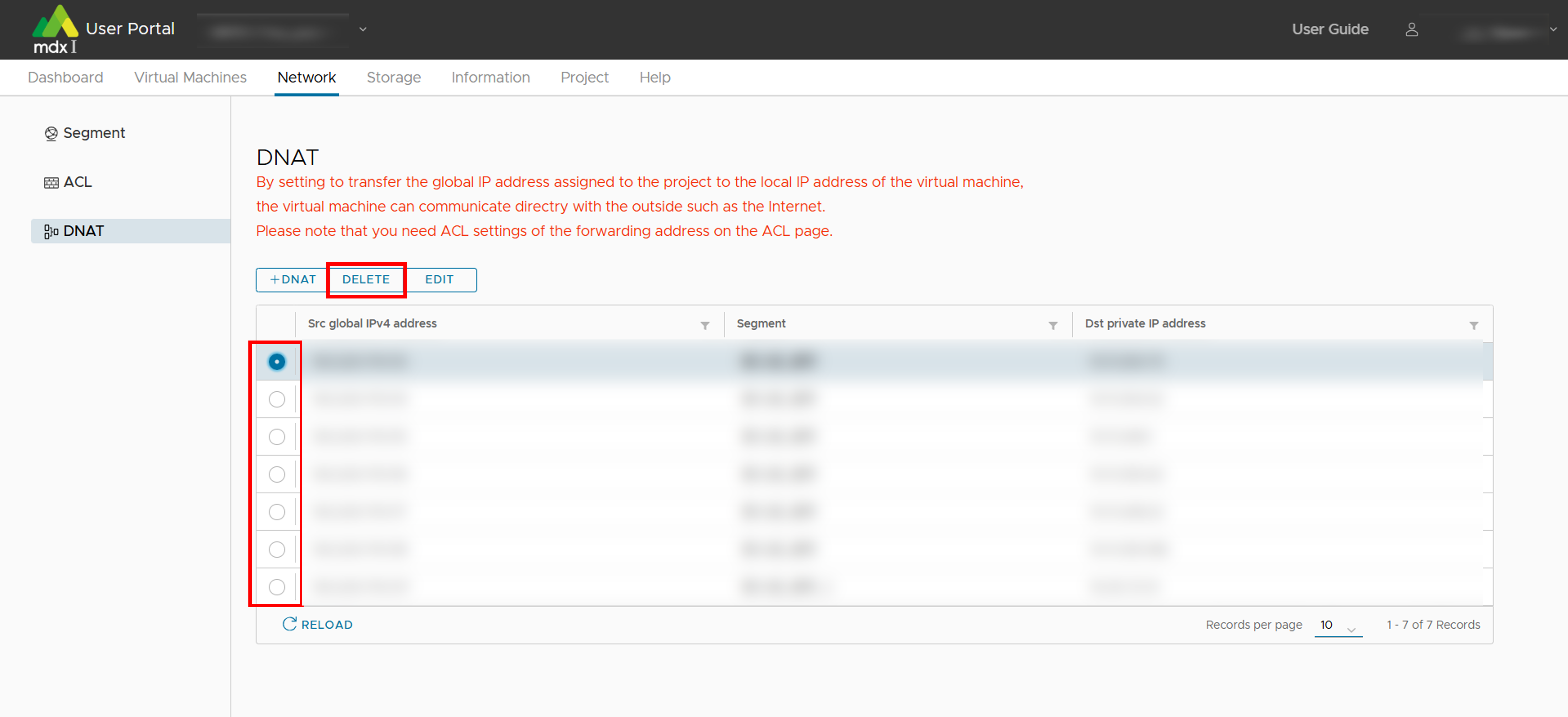
A confirmation screen will be displayed, so if there are no issues, click [YES].
10.5.3.3. Changing DNAT settings
Click [EDIT] with any DNAT setting you want to change being selected.
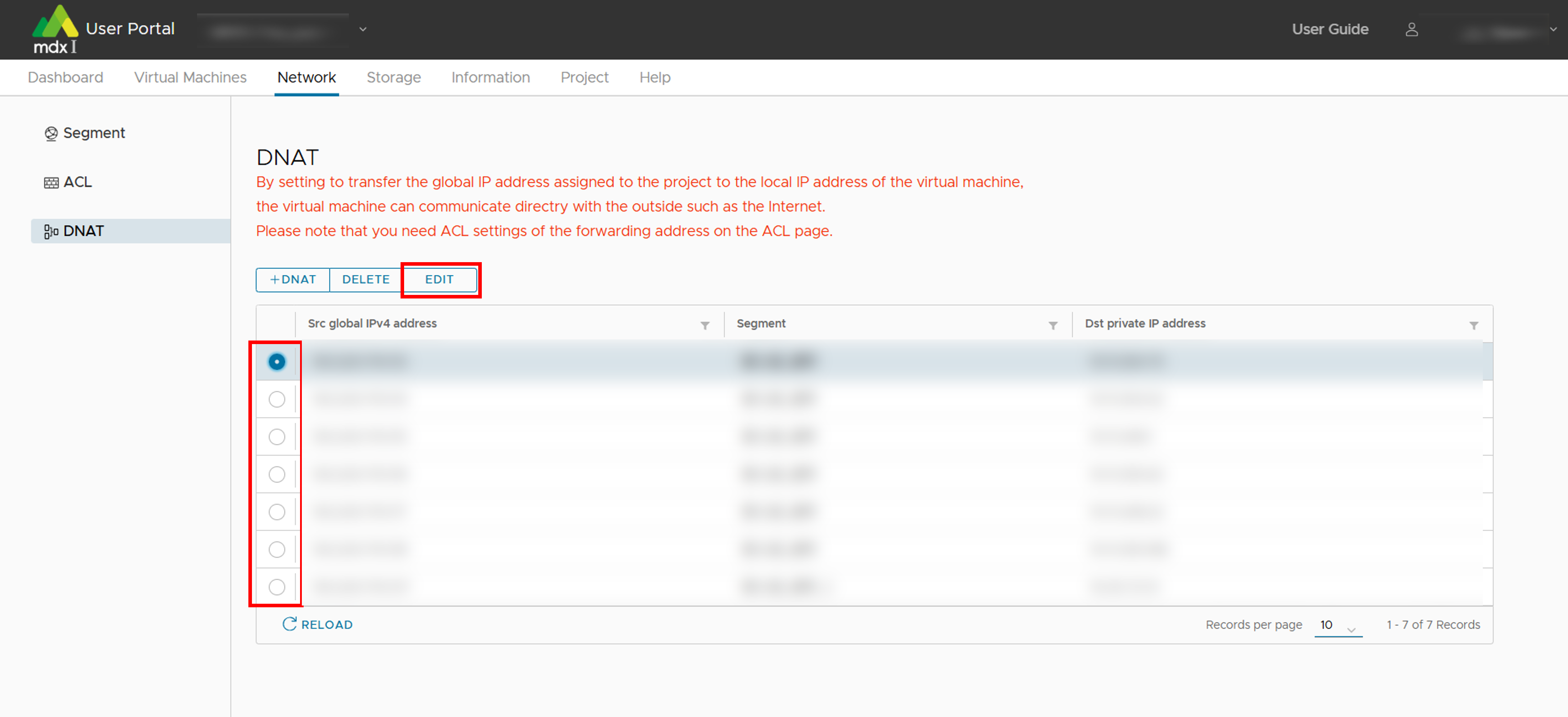
Update the setting item you want to change.
Click [EDIT] when you are completed.
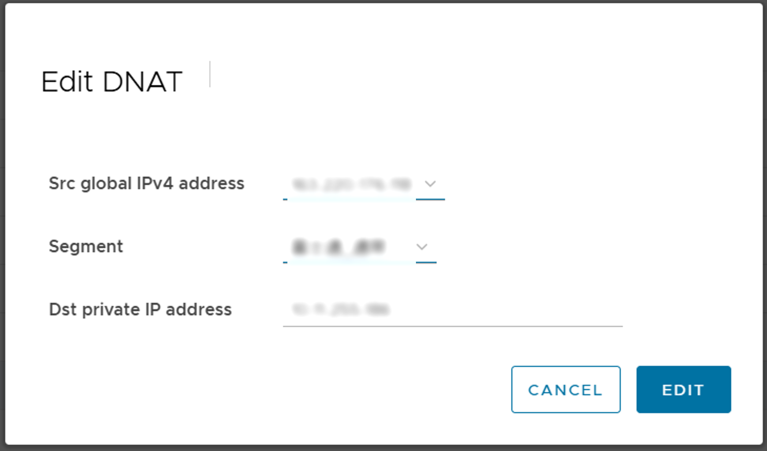
10.6. Confirmation of storage usage status and apply for additional storage
This chapter describes the procedure for configuring settings related to storage usage. These settings can be confirmed from the screen by clicking on [Storage] from the top menu.
10.6.1. Confirm the storage usage status
Storage usage can be confirmed from [Storage] in the side menu.
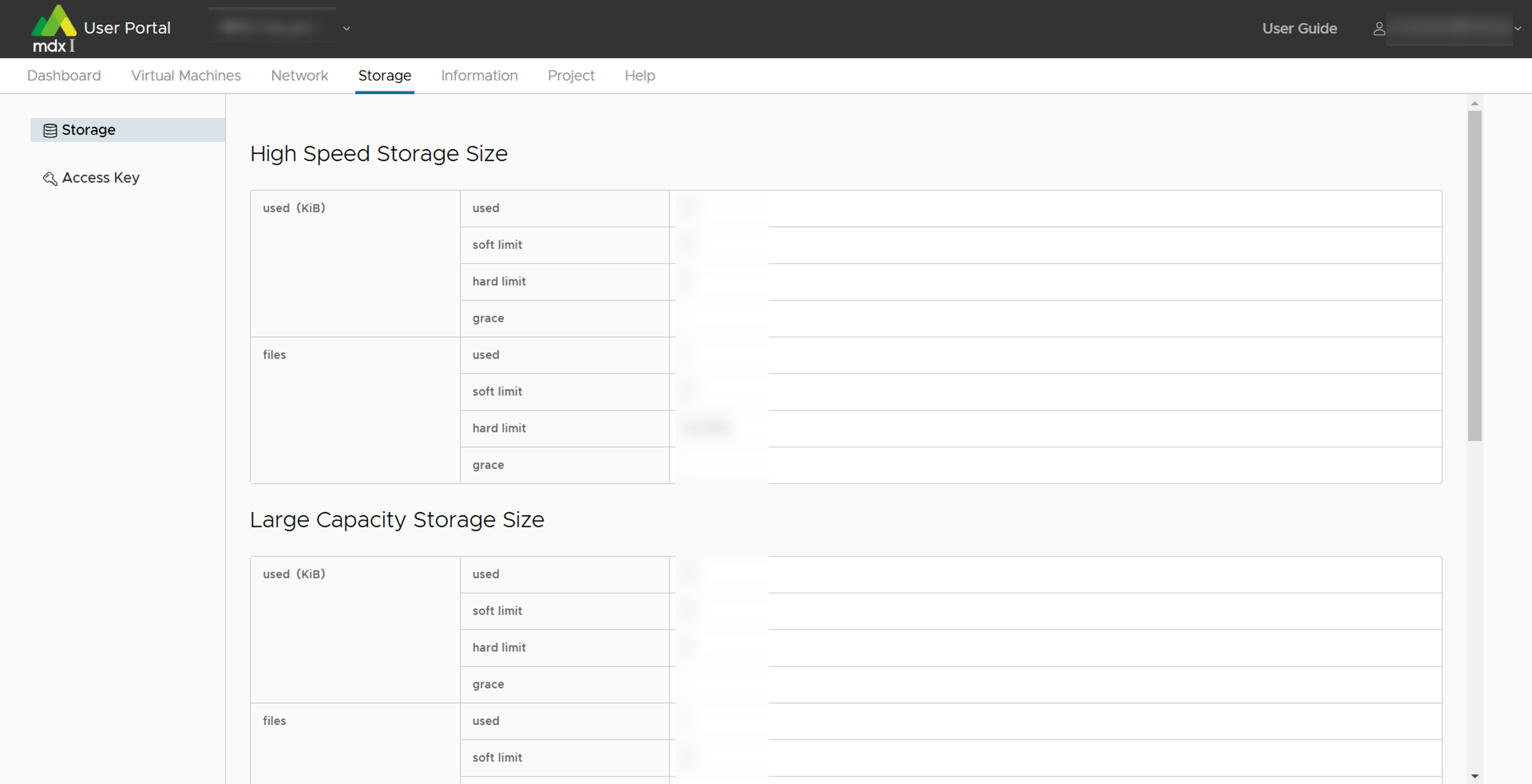
Also, additional storage usage can be applied from the [APPLY OBJECT STORAGE] at the bottom of the main screen.
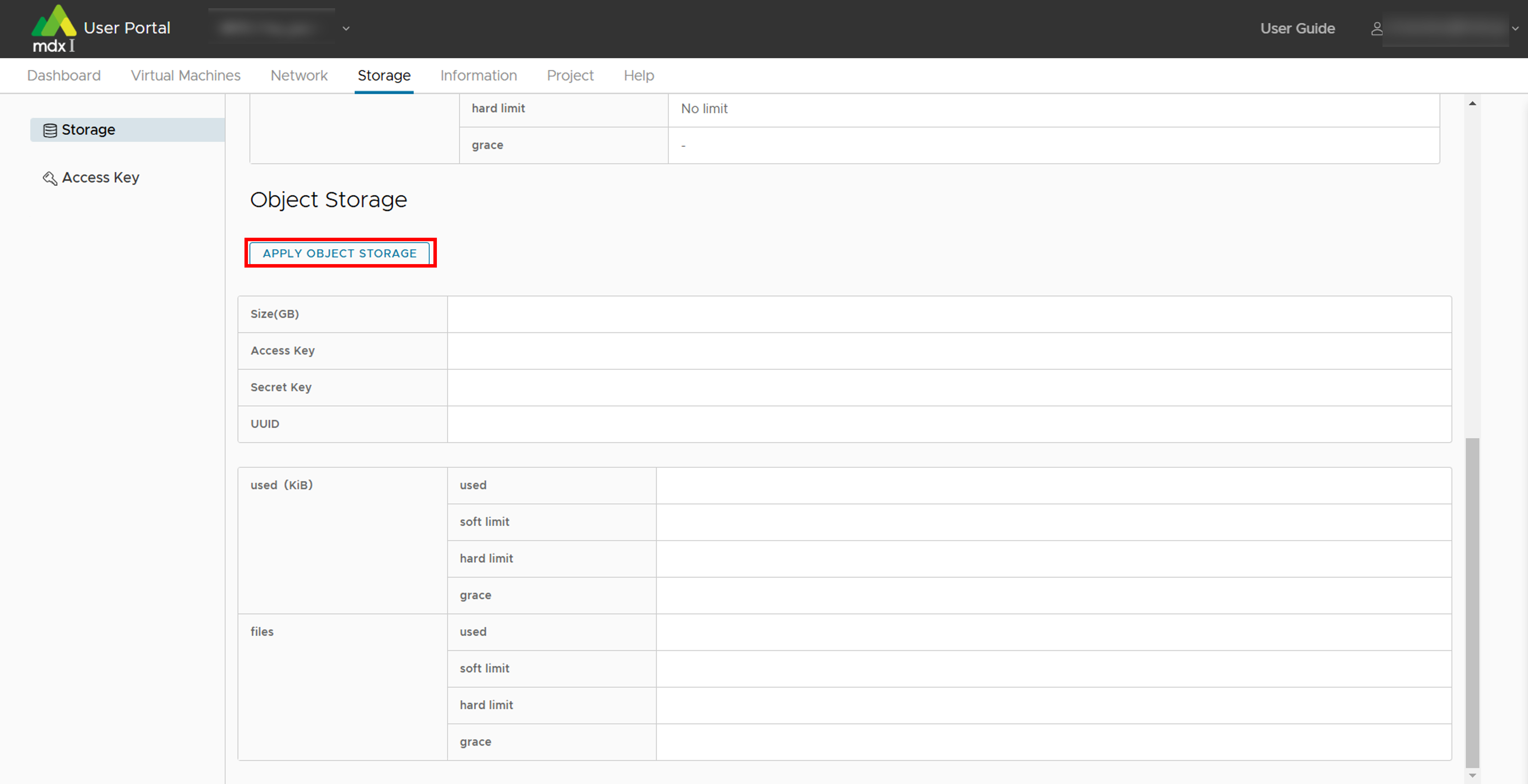
Specify the size of storage to be applied for in GB.
Confirm that there are no issues with the application contents and click [APPLY]. This completes the object storage application.
10.6.2. Confirm/add key to access object storage.
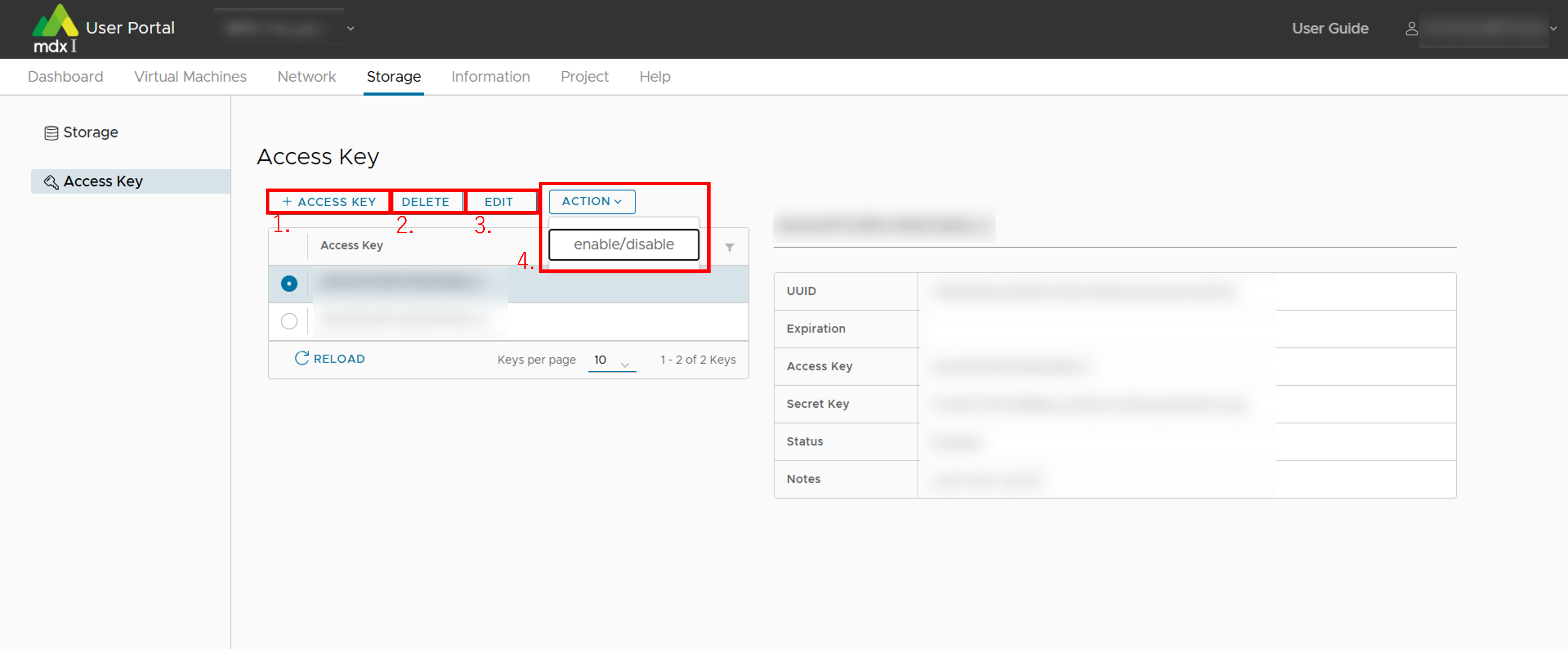
Add an access key
When adding, set the expiration date of the access key at the same time
Delete the access key
Change the expiration date of the access key
Switch between enable/disable status of the access key
10.7. Functions to confirm and modify projects
Note
10.7.1. Review and change project information
This function is available from [Project] in the side menu.
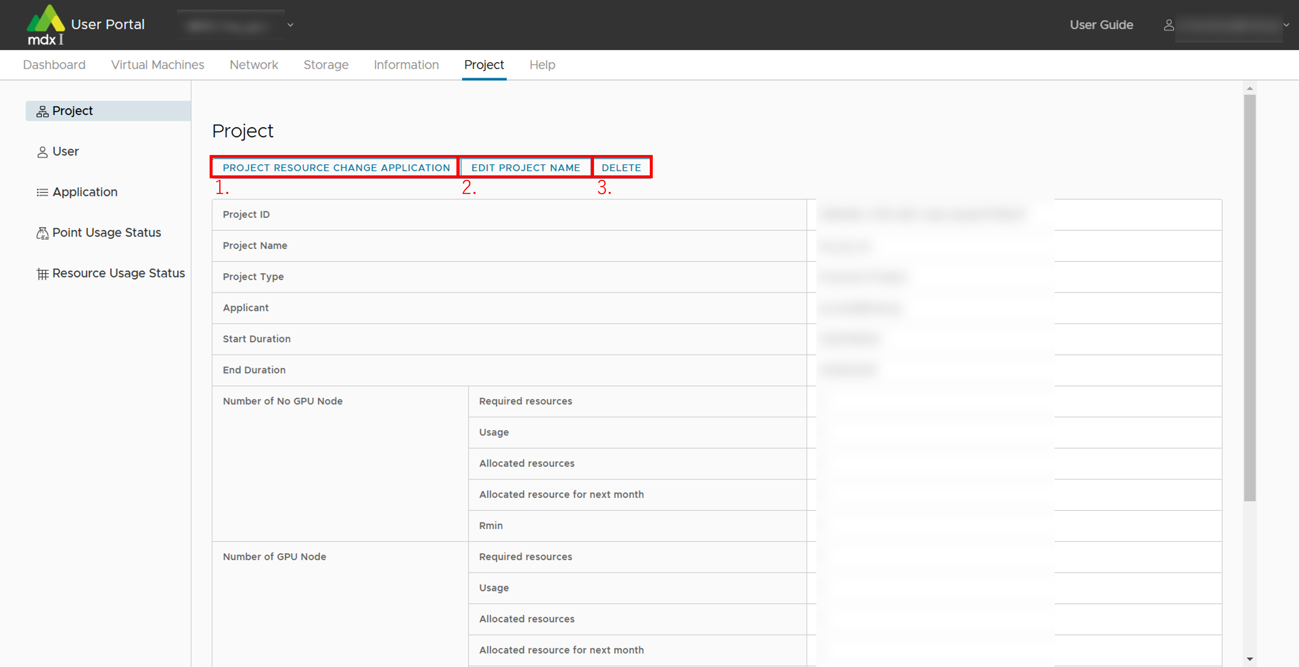
- Apply for project resources application/changes to the project duration.The items that can be set are as follows. This application can be performed when the project type is other than “Trial”.
(In the case of Normal Projects) CPU Pack Allocation for Reserved VM Instances
(In the case of Normal Projects) GPU Pack Allocation for Reserved VM Instances
(In the case of Node Occupancy Projects) Generic CPU Nodes
(In the case of Node Occupancy Projects) GPU Acceleration Nodes
Virtual Disk Storage (GB)
High-Speed Storage (GB)
Large-Capacity Storage (GB)
Global IP Addresses
End Duration
Change the project name
Delete project
Note
When a project is deleted, all virtual machines are also deleted and no longer accessible.Please note that deleted virtual machines cannot be recovered.
10.7.1.1. About the resources that can be applied for
You can apply for resources marked with “〇” below for each project type.
Resources |
Normal |
Node Occupancy |
|---|---|---|
CPU Pack Allocation for Reserved VM Instances |
〇 |
- |
GPU Pack Allocation for Reserved VM Instances |
〇 |
- |
Generic CPU Nodes |
- |
〇 |
GPU Acceleration Nodes |
- |
〇 |
Virtual Disk Storage |
〇 |
〇 |
High-Speed Storage |
〇 |
〇 |
Large-Capacity Storage |
〇 |
〇 |
Global IP Addresses |
〇 |
〇 |
If a Reserved Virtual Machine was deployed at the time of the above resource release, it will be automatically changed to a Spot Virtual Machine.
After releasing the resources, if you want to use CPU Pack or GPU Pack for the Reserved Virtual Machine, apply for the resources again.
Name |
Number of virtual CPUs |
Amount of virtual memory |
Number of GPUs |
|---|---|---|---|
Generic CPU Nodes |
152 |
Approx. 256GB |
0 |
GPU Acceleration Nodes |
152 |
Approx. 512GB |
8 |
The maximum number of CPUs and GPUs that can be assigned to a single virtual machine is 152 CPUs and 8 GPUs.
10.7.2. Check and change users who belong to a project
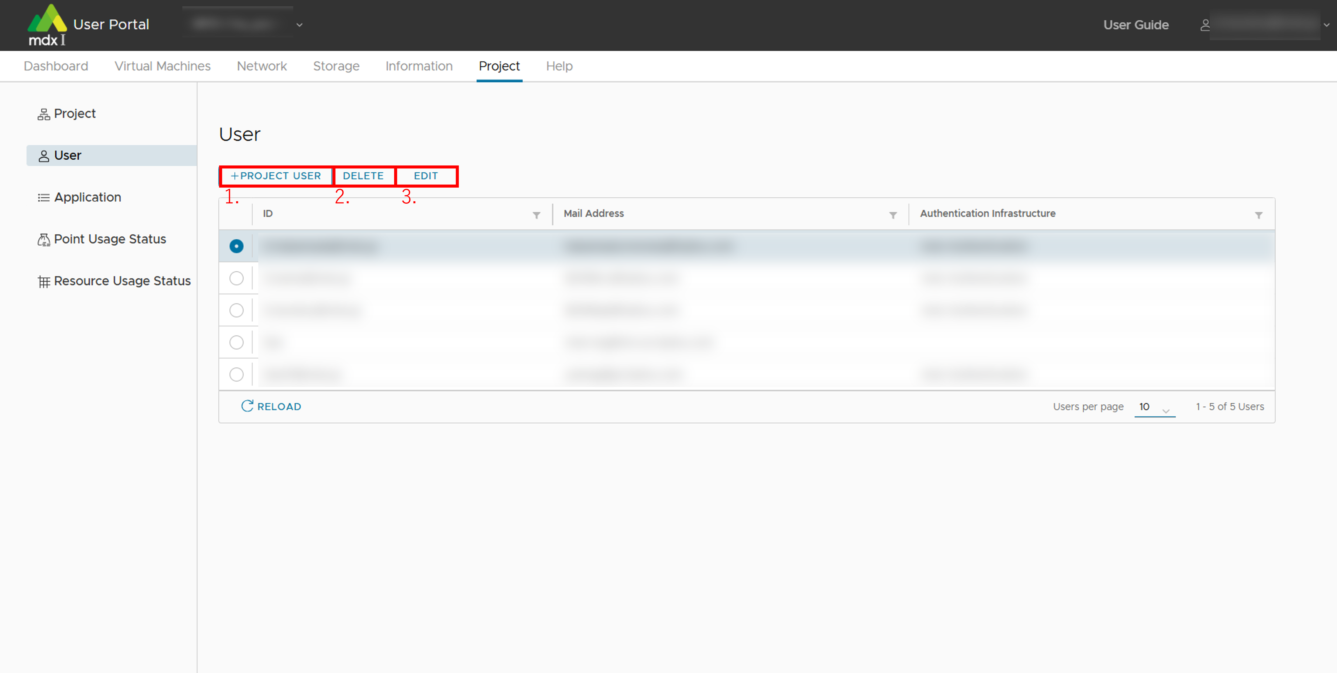
- Add a new user to the projectThe following items can be set
Authentication Infrastructure: Specify the type of account you are using, either GAKUNIN or mdx authentication platform.
GAKUNIN ID or mdx Authentication ID: Name to identify the user.
Mail Address: User’s contact mail address.
Removes the user selected in the list from the project.
Edit the information of the user selected in the list.
10.7.3. Check the status of your application.
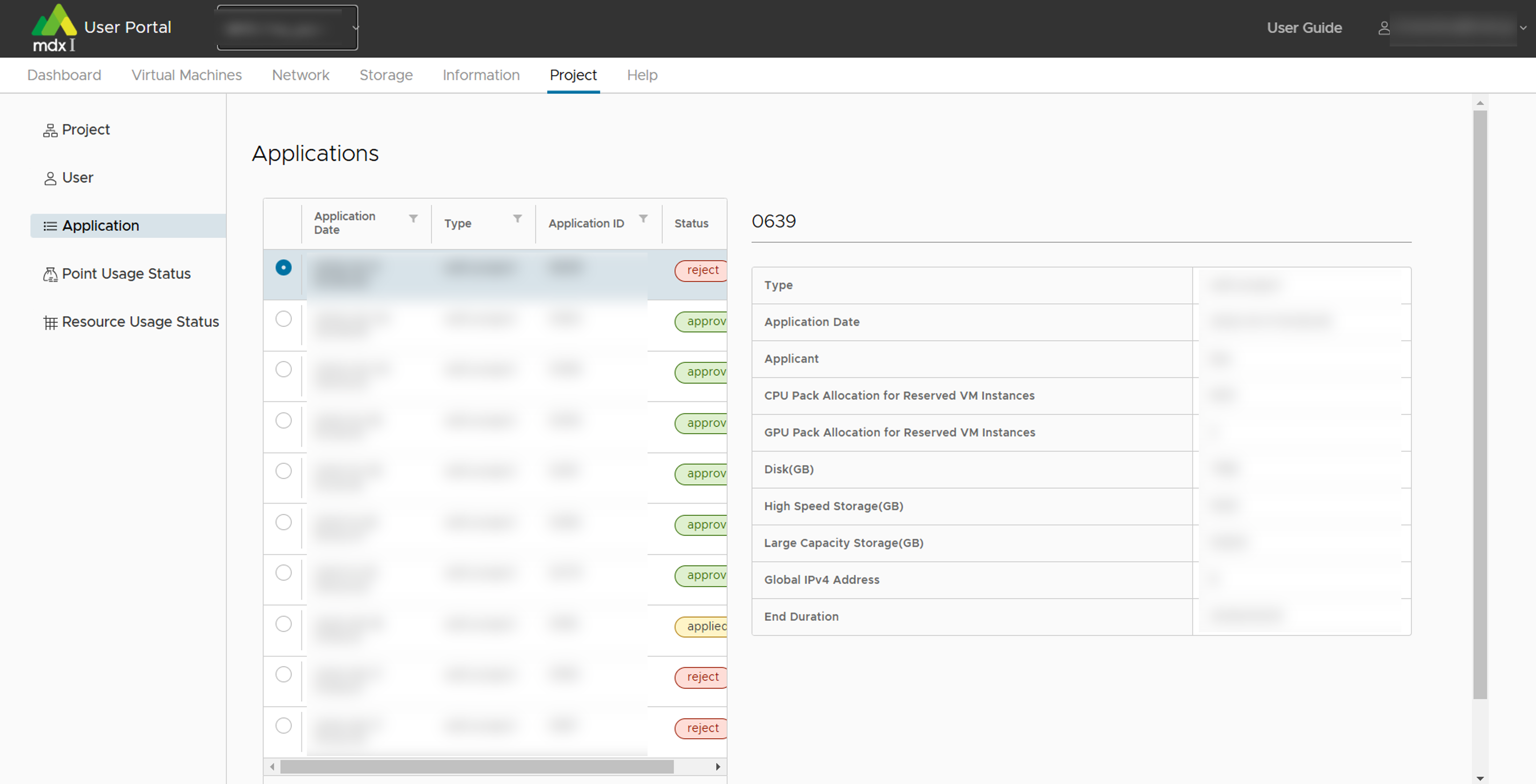
The current status of each application will be displayed in the [Status] column as follows.
applied
approved
reject
10.7.4. Check the status of points held by the project
You can check the current status of points held by the project. This function is available from [Point Usage Status] in the side menu.
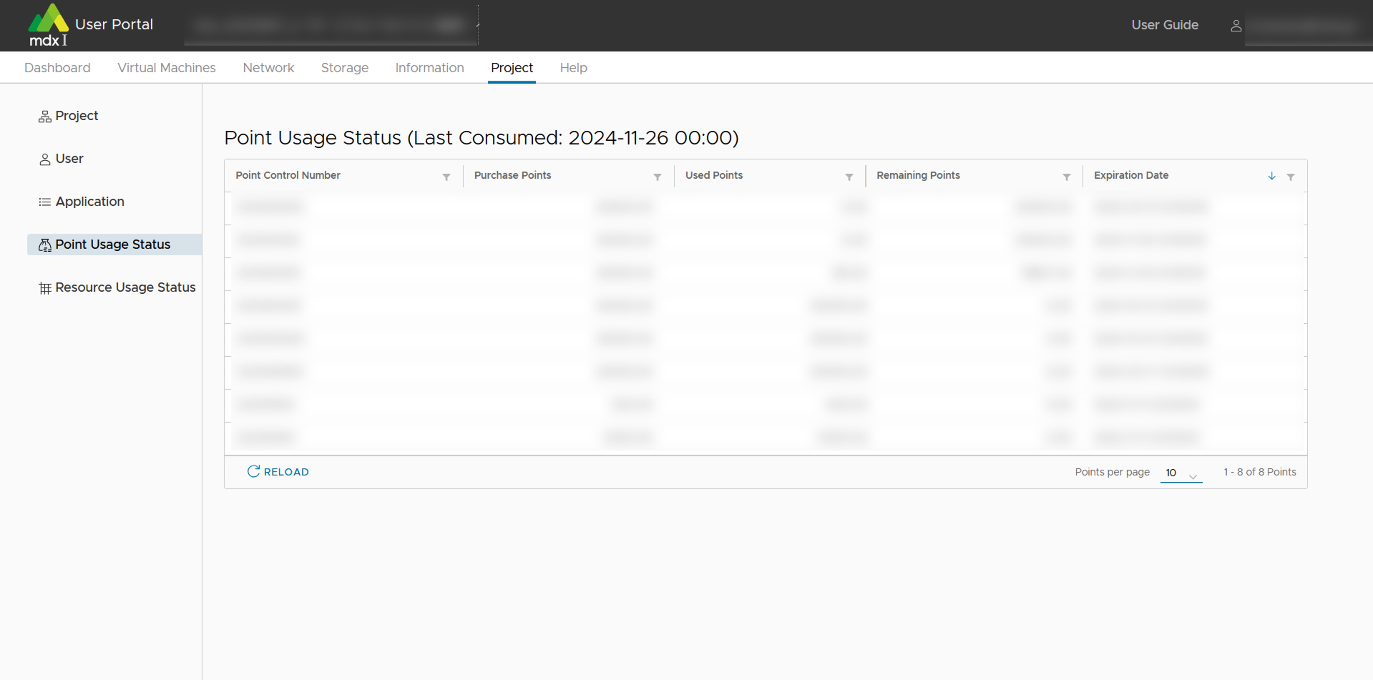
Items that can be checked include.
Point Control Number
Purchase Points
Used Points
Remaining Points
Expiration Date
10.7.5. Check the use of resources
You can check the amount of resources used and points consumed within a specified period. This function is available from [Resource Usage Status] in theside menu.
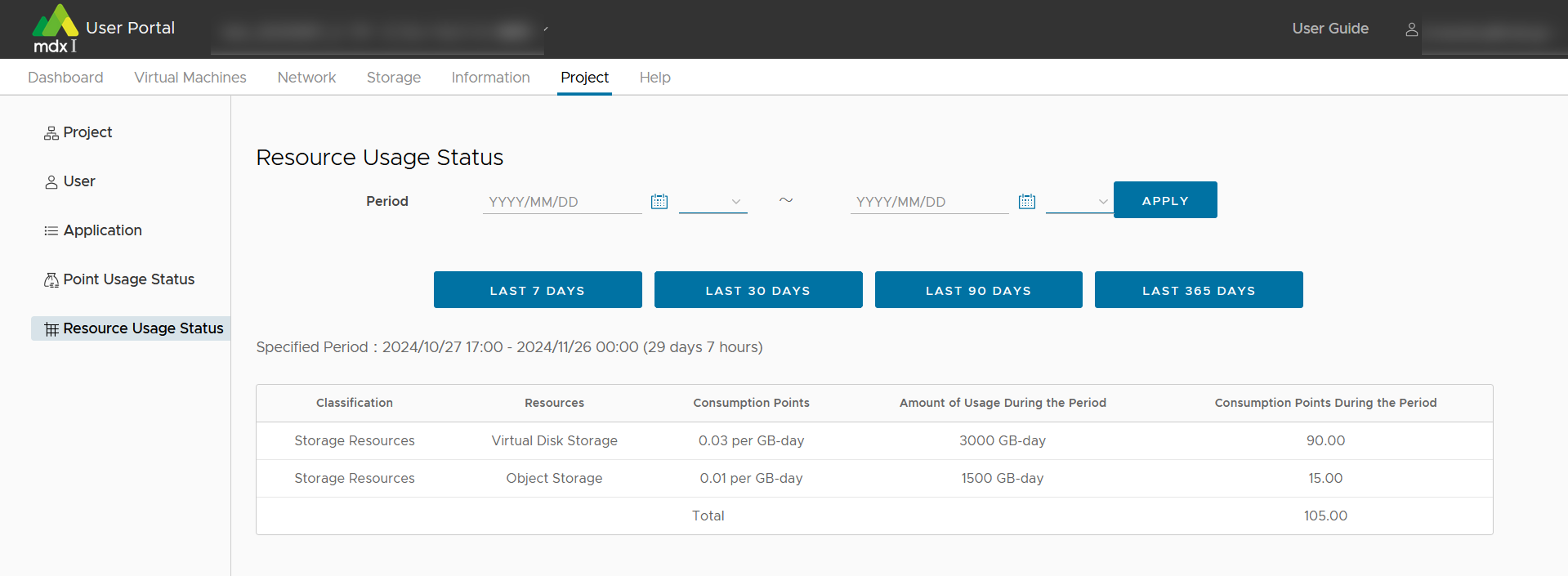
You can check the resource usage by specifying the start/end date and time and clicking [APPLY].
If you want to know the results for the period of 7, 30, 90, or 365 daysup to the time of this function use, you can also click on [LAST (Number) days].
10.8. About other Functions
10.8.1. Information
This information can be confirmed from the screen by clicking on [Information] from the top menu.
10.8.1.1. Confirm notification from the portal administrator
You can check announcements from the portal administrator, such as information about scheduled system maintenance.
10.8.1.2. Confirm the progress status and history of operations performed on the user portal
You can check the progress and, if completed, the results of various operations you have performed on the user portal.
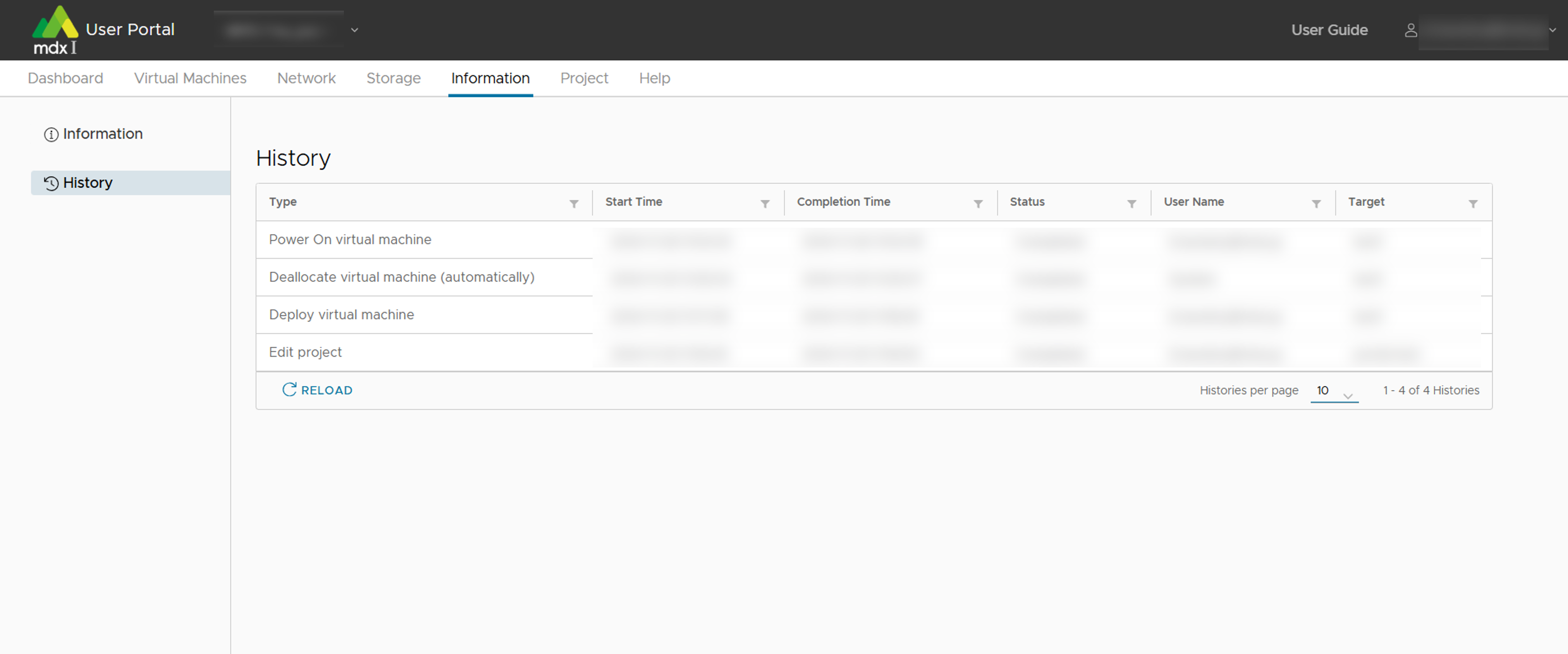
Type |
User Name |
Operation Description |
|---|---|---|
Deallocate virtual machine |
System |
Automatic shutdown due to resource capture |
Deallocate virtual machine |
System |
Automatic pause due to resource reallocation |
Deallocate virtual machine |
System |
pause in move processing when maintenance flag is set |
Deallocate virtual machine (Project Period End) |
System |
Automatic suspension due to end of project period |
Deallocate virtual machine (Project Stop) |
System |
Automatic pause by stopping a project |
Deallocate virtual machine (automatically) |
System |
Resource deallocation for powered-off Spot Virtual Machines |
Deploy virtual machine |
user name |
Deploy virtual machines |
Create virtual machine |
user name |
Deployment Operations with Templates (ISO Images) |
Power On virtual machine |
user name |
Power-on a Virtual Machine |
Rename virtual machine |
user name |
Change the virtual machine name |
Delete virtual machine |
user name |
Delete a virtual machine |
Power Off virtual machine |
user name |
Power-off a Virtual Machine |
Reset virtual machine |
user name |
Power-on operation after power-off processing of the virtual machine |
Shutdown Guest OS |
user name |
Shutdown a Virtual Machine |
Restart Guest OS |
user name |
Power-on after virtual machine shutdown |
Reconfigure virtual machine |
user name |
Change the settings for each virtual machine resource |
Console |
user name |
Console display |
Clone virtual machine |
user name |
Cloning Virtual Machines |
Upload ISO |
user name |
Upload ISO |
Mount ISO |
user name |
Mounting an ISO Image to a Virtual Machine |
Unmount ISO |
user name |
Unmount an ISO image to a Virtual Machine |
Export OVF |
user name |
Virtual Machine OVF Image Export |
Import OVF |
user name |
Virtual Machine OVF Image Import |
Edit DNAT |
user name |
Network DNAT Settings |
Add ACL (IPv4) |
user name |
Adding a New ACL (IPv4) for a Network |
Edit ACL (IPv4) |
user name |
Changing ACL (IPv4) Settings for a Network |
Add ACL (IPv6) |
user name |
Adding a New ACL (IPv6) for a Network |
Edit ACL (IPv6) |
user name |
Changing ACL (IPv6) Settings for a Network |
Add segment |
user name |
Adding Network Segments |
Edit project |
user name |
Application for editing project information |
Add user |
user name |
Adding Project Users |
Edit user |
user name |
Editing Project User Information |
Change password |
user name |
Change Project User Password |
Apply object storage |
user name |
Application for object storage |
Edit access key |
user name |
Edit object storage access key notes and expiration dates |
Enable access key |
user name |
Enabling Access Keys for Object Storage |
10.8.2. Help
Inquire to the administrator by e-mail. When you launch the mailer from the contact screen, the information necessary for the inquiry is automatically inserted into the email body.
Click [Help] from the top menu.
Follow the description on the inquiry form and send an inquiry using the mailer.
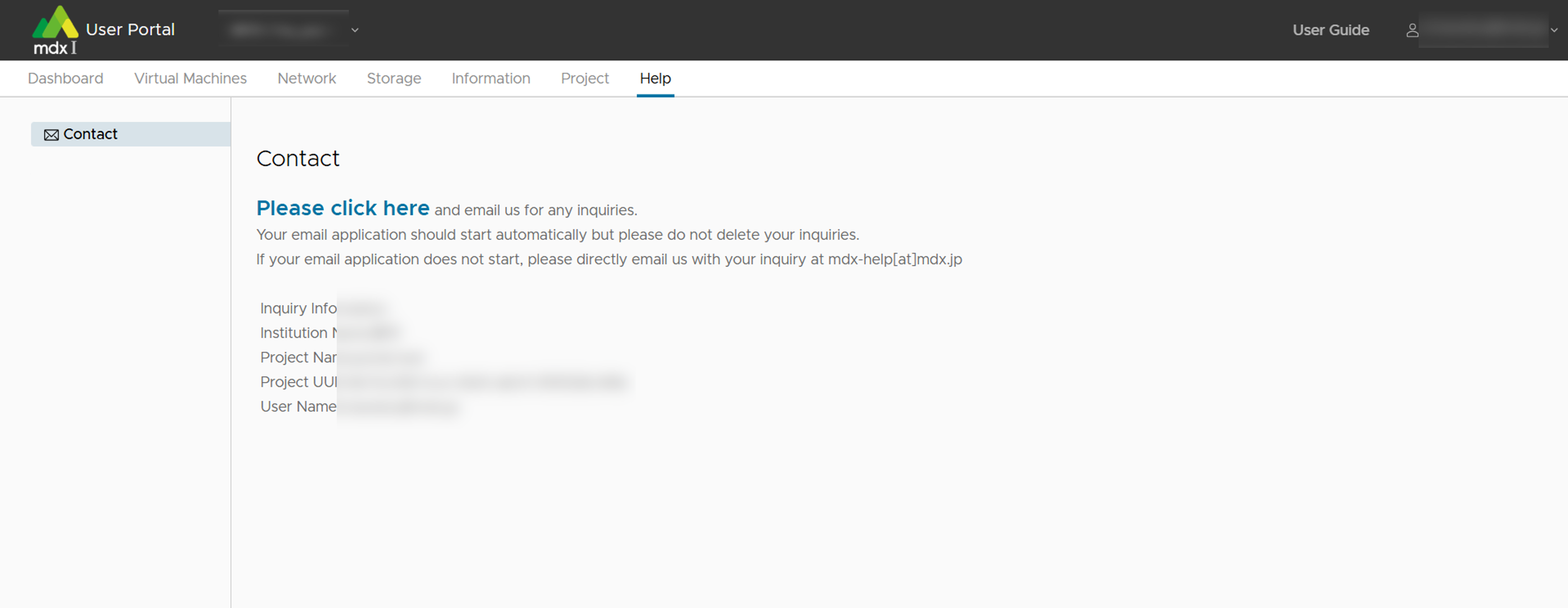
11. Example of creating a cluster with multiple virtual machine
This section explains an example of building a simple cluster using multiple virtual machines deployed on mdx.
11.1. Ansible and its overview
Here is an example of deploying and configuring multiple VMs on mdx using one such provisioning tool, Ansible .
The minimum files required to execute Ansible are,
- playbook
A file in YAML format describing the process to execute on the machine to be set
- inventory
A file describing the IP address and additional information of the machine to be configured.
The above two are necessary.
deploy-jupyter.yaml as a playbook, which describes the process required to deploy Jupyterlab.hosts as an inventory describing the IP addresses of the VMs you want to execute the process on, and type ansible-playbook -i hosts deploy-jupyter.yaml and you can launch Jupyterlab on multiple VMs.ansible-playbook command (or the ansible command) to configure/control other hosts is called a Control node, and conversely, a host (in this case a VM) that is set/controlled by a Control node is called a Managed node. +---------+
playbook.yaml | |
hosts | Managed |
+---------+ +----->| node1 |
| | | | |
| Control | ssh | +---------+
| node +-----+
| | | +---------+
+---------+ | | |
| | Managed |
+----->| node2 |
| |
+---------+
ansible-playbook command, then two Managed Nodes are configured over ssh.11.2. https://github.com/mdx-jp/machine-configs
Note
Currently all playbook are intended to be executed against VM created from the ubuntu server 22.04 template.
ansible-playbook and the required number of VMs (Managed Node) that will be part of the cluster, with reference to the Virtual machine usage flow .In the figure below, a node called test is used to run the ansible-playbook , and eight VMs, vm1 to vm8 to form a cluster, are deployed from the ubuntu-2204-server template. vm1 to vm8 were deployed at once by entering vm[1-8] as the virtual machine name when deploying VMs.
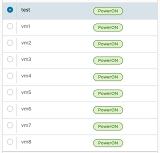
Please implement ACL settings, ssh public key submission, etc. according to your own environment by referring to Network setting and Virtual machine usage flow .
When connecting to OpenMPI and Lustre storage with RDMA, please create a storage network with SR-IOV.
11.3. Cluster Configuration: Preparation
11.3.1. Ansible Installation
ansible-playbook (in the above example, the VM named test) and install Ansible (we first changed the hostname for clarity).ssh-A) or similar to ssh into this host so that you can ssh into each VM from this host with mdxuser.mdxuser@ubuntu-2204:~$ sudo hostnamectl set-hostname ansible
mdxuser@ubuntu-2204:~$ bash
mdxuser@ansible:~$ sudo apt install ansible
Reading package lists... Done
Building dependency tree
Reading state information... Done
Suggested packages:
cowsay sshpass
The following NEW packages will be installed:
ansible
0 upgraded, 1 newly installed, 0 to remove and 17 not upgraded.
Need to get 5794 kB of archives.
After this operation, 58.0 MB of additional disk space will be used.
Get:1 http://jp.archive.ubuntu.com/ubuntu focal/universe amd64 ansible all 2.9.6+dfsg-1 [5794 kB]
Fetched 5794 kB in 1s (4666 kB/s)
Selecting previously unselected package ansible.
(Reading database ... 125879 files and directories currently installed.)
Preparing to unpack .../ansible_2.9.6+dfsg-1_all.deb ...
Unpacking ansible (2.9.6+dfsg-1) ...
Setting up ansible (2.9.6+dfsg-1) ...
Processing triggers for man-db (2.9.1-1) ...
11.3.2. Acquire machine-configs repository
Next clone the machine-configs Git repository where the playbook is prepared and move it there.
mdxuser@ansible:~$ git clone https://github.com/mdx-jp/machine-configs
Cloning into 'machine-configs'...
remote: Enumerating objects: 785, done.
remote: Counting objects: 100% (785/785), done.
remote: Compressing objects: 100% (510/510), done.
remote: Total 785 (delta 376), reused 622 (delta 214), pack-reused 0
Receiving objects: 100% (785/785), 119.50 KiB | 9.96 MiB/s, done.
Resolving deltas: 100% (376/376), done.
mdxuser@ansible:~$ cd machine-configs/
mdxuser@ansible:~/machine-configs$ ls
ansible.cfg mdxcsv2inventory.py playbook.yml roles
files mdxpasswdinit.py README.md vars
11.3.3. Inventory file creation
mdxcsv2inventory.py to easily create this inventory file.When you provide the downloaded CSV file to mdxcsv2inventory.py , it generates an inventory file listing the VMs mentioned in the CSV file as Managed Nodes.
mdxuser@ansible:~/machine-configs$ ./mdxcsv2inventory.py user-portal-vm-info.csv
[all:vars]
ansible_user=mdxuser
ansible_remote_tmp=/tmp/.ansible
ethipv4prefix=10.13.200.0/21
rdmaipv4prefix=10.141.200.0/21
ethipv6prefix=2001:2f8:1041:21e::/64
[default]
10.13.204.85 hostname=vm1 ethipv4=10.13.204.85 rdmaipv4=10.141.200.147
10.13.204.83 hostname=vm2 ethipv4=10.13.204.83 rdmaipv4=10.141.200.146
10.13.204.89 hostname=vm3 ethipv4=10.13.204.89 rdmaipv4=10.141.204.70
10.13.200.158 hostname=vm4 ethipv4=10.13.200.158 rdmaipv4=10.141.204.63
10.13.204.90 hostname=vm5 ethipv4=10.13.204.90 rdmaipv4=10.141.200.149
10.13.204.87 hostname=vm6 ethipv4=10.13.204.87 rdmaipv4=10.141.200.150
10.13.204.84 hostname=vm7 ethipv4=10.13.204.84 rdmaipv4=10.141.204.64
10.13.204.86 hostname=vm8 ethipv4=10.13.204.86 rdmaipv4=10.141.204.67
[default] indicates a group. In Ansible, the hosts are grouped in the inventory file, and in the playbook, and the playbook is described what process to perform for the group.mdxcsv2inventory.py creates this [default] as a group describing all VM addresses.hosts.ini for later use.mdxuser@ansible:~/machine-configs$ ./mdxcsv2inventory.py user-portal-vm-info.csv > hosts.ini
11.3.4. Preparation before executing Ansible
mdxpasswordinit.py included in machine-configs to setup initial passwords for all hosts in the [default] group of the inventory file at once.mdxuser@ansible:~/machine-configs$ ./mdxpasswdinit.py ./hosts.ini
Target hosts: 10.13.204.85, 10.13.204.83, 10.13.204.89, 10.13.200.158, 10.13.204.90, 10.13.204.87, 10.13.204.84, 10.13.204.86
New Password:
Retype New Password:
initializing the first password...
10.13.204.85: Success
10.13.204.83: Success
10.13.204.89: Success
10.13.200.158: Success
10.13.204.90: Success
10.13.204.87: Success
10.13.204.84: Success
10.13.204.86: Success
This operation only needs to be executed once for a VM.
11.4. Playbook preparation and execution
The operations on the VM currently provided by machine-configs are as follows.
Role |
Desciprition |
|---|---|
common |
Setting hostname and /etc/hosts and installing the specified package |
desktop_common |
Install xrdp |
nfs_server |
Make VM an NFS server and export /home |
nfs_client |
Over NFS to mount /home |
ldap_server |
Make the VM an LDAP server and create LDAP account |
ldap_client |
Make the VM an LDAP client and set it to refer to the LDAP server. |
jupyter |
Install jupyterLab and start it as a daemon |
reverse_proxy |
Reverse proxy a VM and forward access to a specific port to a specific port on another VM |
mpi |
Setup to use OpenMPI |
playbook.yml, the block that applies the Role to the host is as follows.- name: setup NFS server
hosts: nfsserver
roles:
- nfs_server
nfs_server Role to a group of hosts called nfsserver.mdxcsv2inventory.py creates only [default] group by default.nfsserver to which one VM belongs.[nfsserver], or you can create a group using mdxcsv2inventory.py as shown below.mdxuser@ansible:~/machine-configs$ ./mdxcsv2inventory.py user-portal-vm-info.csv -g nfsserver vm1
[all:vars]
ansible_user=mdxuser
ansible_remote_tmp=/tmp/.ansible
ethipv4prefix=10.13.200.0/21
rdmaipv4prefix=10.141.200.0/21
ethipv6prefix=2001:2f8:1041:21e::/64
[default]
10.13.204.85 hostname=vm1 ethipv4=10.13.204.85 rdmaipv4=10.141.200.147
10.13.204.83 hostname=vm2 ethipv4=10.13.204.83 rdmaipv4=10.141.200.146
10.13.204.89 hostname=vm3 ethipv4=10.13.204.89 rdmaipv4=10.141.204.70
10.13.200.158 hostname=vm4 ethipv4=10.13.200.158 rdmaipv4=10.141.204.63
10.13.204.90 hostname=vm5 ethipv4=10.13.204.90 rdmaipv4=10.141.200.149
10.13.204.87 hostname=vm6 ethipv4=10.13.204.87 rdmaipv4=10.141.200.150
10.13.204.84 hostname=vm7 ethipv4=10.13.204.84 rdmaipv4=10.141.204.64
10.13.204.86 hostname=vm8 ethipv4=10.13.204.86 rdmaipv4=10.141.204.67
[nfsserver]
# group with regexp 'vm1'
10.13.204.85 hostname=vm1 ethipv4=10.13.204.85 rdmaipv4=10.141.200.147
mdxuser@ansible:~/machine-configs$ ./mdxcsv2inventory.py user-portal-vm-info.csv -g nfsserver vm1 > hosts.ini
-g [GROUPNAME] [VMNAME] option in mdxcsv2inventory.py can be used to create a host group of any name to which the specified VM belongs.[VMNAME] part is a regular expression, so you can create a group to which multiple VM belongs.For roles other than [nfsserver] listed in playbook.yml , create the [ldapserver] group to make it LDAP server, and the [reverproxy] group to make it reverse proxy, following the above procedure.
desktop_common.After creating the inventory and editing the playbook.yml, the following command will cause Ansible to implement the settings for all VM’s.
mdxuser@ansible:~/machine-configs$ ansible-playbook -i hosts.ini playbook.yml
11.5. Role provided by machine-configs
This section explains the Role provided in machine-configs.
11.5.1. common
hostname in inventory.11.5.2. desktop_common
11.5.3. nfs_server
11.5.4. nfs_client
The NFS server to mount will be the VM at the top of the [nfsserver] group.
11.5.5. ldap_server
ldap_groups.csv and ldap_users.csv under the machine-configs/files directory.machine-configs/fils directory.11.5.6. ldap_client
The LDAP server referenced will be the VM at the top of the [ldapserver] group.
11.5.7. jupyter
journalctl--no-pager -u jupyterlab to get a URL with a token from the log at start of jupyterlab.11.5.8. reverse_proxy
8000 + n port to 8888 port of each VM for VMs in the [default] group. User
|
v
mdx Global IPv4
Address
|
|
+---------+ |
| Nginx | |
| (VM) | |
+----+----+ |
| ^ |
| +-----+
| Ethernet Network (Private Address)
+--------------------+------------------+------------------+
| | | |
v v v v
+--------------+ +--------------+ +--------------+ +--------------+
| Jupyterlab | | Jupyterlab | | Jupyterlab | | Jupyterlab | ...
| (VM1) | | (VM2) | | (VM3) | | (VM4) |
+--------------+ +--------------+ +--------------+ +--------------+
reverse_proxy Role applied, it is possible to access the jupyter lab of each VM from the outside.Once mapping DNAT is done, accessing http://[DNAT address]:8001 on the browser will take you to Jupyterlab for VM1 in the figure above, and accessing http://[DNAT address]:80002 will take you to Jupyterlab for VM2.
Also, each Jupyterlab starts without authentication, so please set the appropriate ACL for the Nginx VM that will be the reverse proxy.
By changing vars/reverse_proxy.yml, you can change the group of VM that will be the backend (default is [default]) and the port number to proxy to (default is 8888).
11.5.9. mpi
12. FAQ
12.1. About User portal
12.1.1. Why do virtual machines end up with the same IP address when cloned?
Typically, if the machine-id remains unchanged, the same IP address will be assigned.
Clone procedure
Empty the /etc/machine-id file of the clone source.
Shut down the clone source.
Execute clone
We are currently considering implementing a function to perform this operation automatically. Until this function is implemented, please perform the operation manually.
12.1.2. What if I want to modify the public key I set for my virtual machine?
12.1.3. Not clear as what to set for DNAT and ACL
12.1.4. How can we deal with the need for large amounts of resources in a short period of time?
12.1.5. I have waited a long time for an IP address and it has not been assigned. The one that was assigned is suddenly gone.
In general, there are two major possible causes.
Possibility that IP address cannot be paid out for some reason due to system failure
In this case, the problem is often not only with a particular virtual machine, but with the whole system.Please check if other virtual machines are also experiencing the same problem of IP address not being paid out or not being displayed.Possibility that the IP address is not visible due to an OS problem.
If the OS network settings are incorrect or the OS hangs,VMware Tools cannot fetch the correct information and it becomes impossible to confirm the IP address on the portal.In this case, please reboot the OS or restart the network interface from the console.If it is not an OS problem, please contact us.When making an inquiry, please include the status of the OS (inaccessible, just after reboot, etc.) so that we can begin our investigation smoothly.
12.1.6. Error finding storage when installing OS from ISO image
12.1.7. Creation of a new virtual machine that uses a GPU pack fails with an error.
When creating (deploying) a new virtual machine that uses the GPU pack, the message “No available ESXi found.” is displayed and deployment fails.
Virtual machines run on an ESXi host, which (in the case of GPUs, also as physical nodes) has a maximum of virtual machines using 8 GPU packs. Also, due to operational specifications, the ESXi host may run multiple users virtual machines on the same ESXi host, and depending on the number of GPU packs specified, the ESXi host may share resources with other users. Therefore, depending on the availability of GPU resources, there may be cases where the environment does not satisfy the specified number of GPU packs and the creation of a virtual machine fails.
If the creation of a virtual machine fails, please review the number of GPU packs to be specified (reduce the number from the original number) and check by creating a new virtual machine (deploy) again.
Please note that the maximum number of GPU packs that can be used at one time varies depending on usage conditions.
12.1.8. The number of GPU packs in the virtual machine was changed (increased), but an error occurred and the number could not be increased.
Select the target virtual machine in the user portal - “Virtual Machines” - “Control” screen.
(If the virtual machine was started by the user) Execute “Power” - “Shut Down” from the list displayed by “ACTION” on the operation icon. (The virtual machine can be shut down by using the OS Shutdown command also)
After stopping the virtual machine, perform “Maintenance” - “Deallocate” from “ACTION” in the same way.
After completing the hibernation of the virtual machine, in the same way, from “ACTION”, select “Reconfigure” from “ACTION” to change the number of GPU packs.
Please start the virtual machine and confirm that it is available for use.
12.1.9. The virtual machine does not start even when powered on. The operation history status does not progress beyond 10%, and shutdown operations are also not possible.
12.1.10. I received the notification email for forced shutdown of a Spot Virtual Machine, but why isn’t the target machine stopped even at the stop time?
The forced shutdown process for Spot Virtual Machines will be carried out according to this periodic processing rule .
The resources required to start VM-A can be secured without stopping VM-B.
VM-A aborts startup.
If any of the above cases apply, VM-B will be excluded from forced shutdown targets.
12.1.11. Are there any restrictions on specifying virtual machine templates when using NVLink?
10_Rocky9 (Vendor)
10_Ubuntu 22.04 LTS (Vendor)
10_Ubuntu 24.04 LTS (Vendor)
12.2. About Connection to virtual machine
12.2.1. How can I connect to a running virtual machine via ssh from my environment?
Note that this setting is an important security-related setting. Please make each setting at the user’s own responsibility.
12.2.2. How to transfer files between the desktop and the virtual machine?
12.2.3. After ssh login to the virtual machine, it disconnects after a certain period of time. Please tell us how to respond.
The firewall in mdx is set to disconnect if no communication occurs for more than 30 minutes.
Please refer to the following to prevent disconnection due to no communication on the server or client side.
In case of Windows, configure keep-alive settings within SSH client (Putty, TeraTerm, etc,.).
Configure sshd_config and ssh_config on the server side (ClientAliveInterval, ClientAliveCountMax).
12.3. About virtual machine environment setting
12.3.1. We want to set a static address for a virtual machine.
When setting a static address for a virtual machine, you must first check the following information.
IP address to set for the virtual machine
From among the IP addresses provided for the segments configured for the virtual machine,specify an IP address whose host address is in the range of 1~100.- To confirm the segment set for a virtual machine, click [Virtual Machines] in the top menu, select optional virtual machine from the list of virtual machines displayedon the main screen and confirm Service Network > Segment in the summary information on the right side of the screen.
- The IP address range to be assigned to a segment can be confirmed by clicking on the top menu [Network], selecting the segment confirmed above from thelist of segments displayed on the main screen, and then confirming the IP address range displayed on the right.
Example) If the IP address range is mentioned as “10.12.120.0/21”,the IP address is specified as “10.12.120.1” ~ “10.12.120.100”.The IP addresses used for other various network settings are as follows.
- Default gateway address: This is the second to last address in the IP address range provided for the segment set for the virtual machine.Example) If the IP address range is mentioned as “10.12.120.0/21”, it is 10.12.127.254.
- Broadcast address: This is the last address in the IP address range provided for the segment set for the virtual machine.Example) If the IP address range is mentioned as “10.12.120.0/21”, it is 10.12.127.255.
NTP Server: Please use 172.16.2.[26,27].
DNS server: Please use 172.16.2.[26,27]. Or use Public DNS (Example, Public DNS server 8.8.8.8 provided by Google).※
※If a global IP address is set by DNAT,access to the Public DNS servers mentioned above will be disabled, so name resolving by DNS will not be possible.If you want to use DNAT and Public DNS servers at the same time, please add permission rules for Public DNS servers to the network ACL.ACL filter rule example:Src Address: 8.8.8.8
Src Prefix Length: 32
Src Port: 53
Dst Address: IP address set for the virtual machine
Dst Prefix Length: 32
Dst Port: any
Interface device name of “Service Network 1”
You can check the interface device name by opening the terminal of the virtual machine and executing the “ip -br addr” command.The interface device name is the string displayed in the first column of the line where the IP address of “Service Network 1” is shown.In the following example, if the IP address of “Service Network 1” is “10.18.50.248/21”, the interface device name is “ens192”.
$ ip -br addr lo UNKNOWN 127.0.0.1/8 ::1/128 ens192 UP 10.18.50.248/21 metric 100 2001:2f8:1041:2ab:250:56ff:feb0:62ba/64 fe80::250:56ff:feb0:62ba/64 ens224 UP 10.146.50.88/21 metric 100 fe80::250:56ff:feb0:62bb/64
Next, we will introduce an example of how to set static addresses for each virtual machine template.
12.3.1.1. For the virtual machine template “10_Rocky9 (Vendor)”
Click on [Virtual Machines] from the top menu of the user portal.
Click [CONSOLE] with any virtual machine for which you want to set a static address selected on the main screen.
On the console (Or terminal) of the virtual machine, reserve the nmtui tool.
$ sudo nmtui
Move the cursor to [Edit a connection] and press the Enter key.
Move the cursor to the interface device name of “Service Network 1”, press the Enter key, and confirm that [<Activate>] is displayed on the right side.
Move the cursor to [<Automatic>] on the right side of [IPv4 CONFIGURATION] and press Enter key.
Move the cursor to [<Manual>] among the items displayed and press the Enter key.
Move the cursor to [<Show>] on the right side of [IPv4 CONFIGURATION] and press Enter key.
Select each item and enter the settings determined above. Enter the netmask value in the [Addresses] field as well (Example below).
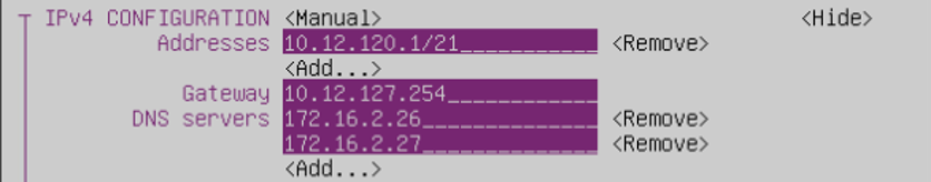
After completing the entry, move the cursor to [<OK>] at the bottom of the screen and press the Enter key.
Move the cursor to [<Back>] at the bottom of the screen and press Enter key.
Move the cursor to [Activate a connection] and press Enter key.
Move the cursor to the interface device name of “Service Network 1”, press the Enter key, and confirm that [<Activate>] is displayed on the right side.
Move the cursor to the interface device name of “Service Network 1”, press the Enter key again, and confirm that [<Deactivate>] is displayed on the right side.
This completes the setup.
12.3.1.2. For the virtual machine template “10_Ubuntu 22.04 LTS (Vendor)” or “10_Ubuntu 24.04 LTS (Vendor)”
Below is an example of how to configure settings when directly editing “/etc/netplan/99-mdx-setup.yaml”.
Open the “/etc/netplan/99-mdx-setup.yaml” file and define a static IP address.
$ sudo vi /etc/netplan/99-mdx-setup.yaml
【Before editing】
network: ethernets: ens224: dhcp4: true ens192: dhcp4: true version: 2
【After editing】
network: ethernets: ens224: dhcp4: true ens192: dhcp4: false addresses: - 10.18.48.51/21 routes: - to: default via: 10.18.55.254 nameservers: addresses: - 172.16.2.26 - 172.16.2.27 version: 2
Reflect settings
$ sudo netplan apply
12.3.2. Is it possible to build an inter-node communication environment using RDMA when specifying a storage network (PVRDMA) in the same way as when specifying a storage network (SR-IOV)?
PVRDMA (Para virtualized RDMA):
RDMA communication between nodes is possible. However, storage (Lustre) is a TCP connection.
SR-IOV:
RDMA communication is used between nodes, including storage (Lustre).
12.3.3. When using nvidia-smi on a GPU virtual machine, GPU-Util is displayed as N/A and some GPUs are not available.
Confirm GPU status (In the following case, MIG is enabled on GPU ID 1, so it cannot be used as a normal GPU (It can be used as a MIG).
mdxuser@ubuntu-2204:~$ nvidia-smi Mon Jul 10 22:11:43 2023 +---------------------------------------------------------------------------------------+ | NVIDIA-SMI 535.54.03 Driver Version: 535.54.03 CUDA Version: 12.2 | |-----------------------------------------+----------------------+----------------------+ | GPU Name Persistence-M | Bus-Id Disp.A | Volatile Uncorr. ECC | | Fan Temp Perf Pwr:Usage/Cap | Memory-Usage | GPU-Util Compute M. | | | | MIG M. | |=========================================+======================+======================| | 0 NVIDIA A100-SXM4-40GB Off | 00000000:03:00.0 Off | 0 | | N/A 24C P0 42W / 400W | 4MiB / 40960MiB | 0% Default | | | | Disabled | +-----------------------------------------+----------------------+----------------------+ | 1 NVIDIA A100-SXM4-40GB Off | 00000000:05:00.0 Off | On | | N/A 24C P0 43W / 400W | 0MiB / 40960MiB | N/A Default | | | | Enabled | +-----------------------------------------+----------------------+----------------------+ | 2 NVIDIA A100-SXM4-40GB Off | 00000000:0D:00.0 Off | 0 | | N/A 25C P0 49W / 400W | 4MiB / 40960MiB | 0% Default | | | | Disabled | +-----------------------------------------+----------------------+----------------------+ | 3 NVIDIA A100-SXM4-40GB Off | 00000000:0F:00.0 Off | 0 | | N/A 25C P0 48W / 400W | 4MiB / 40960MiB | 0% Default | | | | Disabled | +-----------------------------------------+----------------------+----------------------+ +---------------------------------------------------------------------------------------+ | MIG devices: | +------------------+--------------------------------+-----------+-----------------------+ | GPU GI CI MIG | Memory-Usage | Vol| Shared | | ID ID Dev | BAR1-Usage | SM Unc| CE ENC DEC OFA JPG | | | | ECC| | |==================+================================+===========+=======================| | No MIG devices found | +---------------------------------------------------------------------------------------+ +---------------------------------------------------------------------------------------+ | Processes: | | GPU GI CI PID Type Process name GPU Memory | | ID ID Usage | |=======================================================================================| | No running processes found | +---------------------------------------------------------------------------------------+
MIG can be disabled with
sudo nvidia-smi -i <GPU ID> -mig 0. When disabled,MIG devices:will disappear and GPU-Util will go from N/A to 0% as shown below.mdxuser@ubuntu-2204:~$ sudo nvidia-smi -i 1 -mig 0 Disabled MIG Mode for GPU 00000000:05:00.0 All done. mdxuser@ubuntu-2204:~$ sudo nvidia-smi Mon Jul 10 22:15:43 2023 +---------------------------------------------------------------------------------------+ | NVIDIA-SMI 535.54.03 Driver Version: 535.54.03 CUDA Version: 12.2 | |-----------------------------------------+----------------------+----------------------+ | GPU Name Persistence-M | Bus-Id Disp.A | Volatile Uncorr. ECC | | Fan Temp Perf Pwr:Usage/Cap | Memory-Usage | GPU-Util Compute M. | | | | MIG M. | |=========================================+======================+======================| | 0 NVIDIA A100-SXM4-40GB Off | 00000000:03:00.0 Off | 0 | | N/A 24C P0 42W / 400W | 4MiB / 40960MiB | 0% Default | | | | Disabled | +-----------------------------------------+----------------------+----------------------+ | 1 NVIDIA A100-SXM4-40GB Off | 00000000:05:00.0 Off | 0 | | N/A 24C P0 42W / 400W | 4MiB / 40960MiB | 0% Default | | | | Disabled | +-----------------------------------------+----------------------+----------------------+ | 2 NVIDIA A100-SXM4-40GB Off | 00000000:0D:00.0 Off | 0 | | N/A 25C P0 49W / 400W | 4MiB / 40960MiB | 0% Default | | | | Disabled | +-----------------------------------------+----------------------+----------------------+ | 3 NVIDIA A100-SXM4-40GB Off | 00000000:0F:00.0 Off | 0 | | N/A 25C P0 48W / 400W | 4MiB / 40960MiB | 0% Default | | | | Disabled | +-----------------------------------------+----------------------+----------------------+ +---------------------------------------------------------------------------------------+ | Processes: | | GPU GI CI PID Type Process name GPU Memory | | ID ID Usage | |=======================================================================================| | No running processes found | +---------------------------------------------------------------------------------------+
12.3.4. I want to set the root password for the OS (guest OS) installed on the virtual machine.
(base) mdxuser@ubuntu-2204:~$ sudo -s
root@ubuntu-2204:/home/mdxuser# passwd
Changing password for user root.
New password: [新しいパスワードを入力]
Retype new password: [新しいパスワードを再入力]
passwd: all authentication tokens updated successfully.
12.3.5. I want to install VMware Tools on a virtual machine (Windows OS).
Download URL: http://172.16.2.26/
Download the ISO image (VMwareTools_Windows.iso) from “VMwareTools for Windows”
12.4. About various storage usage
12.4.1. Where to confirm the available capacity of High-Speed Storage and Large-Capacity Storage?
12.4.2. Confirmed the usage/upper limit of High-Speed Storage and Large-Capacity Storage using df, but it is not displayed correctly.
For the method on how to confirm, please refer to Confirming the available capacity of High-Speed Storage and Large-Capacity Storage .
12.4.3. What should be done if the virtual machine is started, but fails to mount the Lustre area (/fast, /large)?
Uninstall the built ofed module
$ sudo dkms uninstall -m mlnx-ofed-kernel -v [VERSION] -k $(uname -r)
Delete the source of ofed module
$ sudo dkms remove -m mlnx-ofed-kernel -v [VERSION] -k $(uname -r)
Compile the source of ofed module
$ sudo dkms build -m mlnx-ofed-kernel -v [VERSION] -k $(uname -r)
Install the built ofed module
$ sudo dkms install -m mlnx-ofed-kernel -v [VERSION] -k $(uname -r)
Uninstall the built lustre_client module
$ sudo dkms uninstall -m lustre-client-modules -v [VERSION] -k $(uname -r)
Delete the source of lustre_client module
$ sudo dkms remove -m lustre-client-modules -v [VERSION] -k $(uname -r)
Replace the symbolic link destination of ofa_kernel_headers with the current kernel release information
$ sudo update-alternatives --set ofa_kernel_headers /usr/src/ofa_kernel/x86_64/$(uname -r)
Compile the source of lustre_client module
$ sudo dkms build -m lustre-client-modules -v [VERSION] -k $(uname -r)
Install the built lustre_client module
$ sudo dkms install -m lustre-client-modules -v [VERSION] -k $(uname -r)
Restart the virtual machine
If it does not start after one restart, please wait a little while and restart several times to check the situation.
$ sudo reboot
12.4.4. Please tell the method to make the entire bucket public.
The following is the procedure for making public/private under a bucket at once.
Create a policy for each bucket.
Specify the same values for
Version,Principalas in the following example.Specify any policy name for
Sid.Specifies the bucket name to expose to the
Resource.
Example: (File name: bucket_list.json)
{ "Version": "2008-10-17", "Statement": [ { "Sid": "bucket_list", "Effect": "Allow", "Principal": { "DDN": ["*"] }, "Action": [ "s3:ListBucket", "s3:GetObject" ], "Resource": "bucket_list" } ] }
Apply the created policy to the target bucket.
$ s3cmd --no-check-certificate setpolicy bucket_list.json s3://bucket_list
Confirm that the object is public.
“https://s3ds.mdx.jp/bucket_list/<object name>”
This completes the public settings.
"Effect": "Allow" in the policy file to "Effect": "Deny" and apply the policy.12.5. Virtual machine trouble related
12.5.1. The virtual machine has become unstable. Could it be due to a defect?
12.5.2. When using a specific GPU on a virtual machine, the message “CUDA error: uncorrectable ECC error encountered” is output.
- To confirm the error count, please execute the following command.Check if the value indicated by ★ on any of the GPUs is greater than “0”.
# nvidia-smi -q -d ECC ... GPU 00000000:05:00.0 Ecc Mode Current : Enabled Pending : Enabled ECC Errors Volatile SRAM Correctable : 0 SRAM Uncorrectable : 0 DRAM Correctable : 9 ★ DRAM Uncorrectable : 11 ★ Aggregate SRAM Correctable : 0 SRAM Uncorrectable : 0 DRAM Correctable : 9 DRAM Uncorrectable : 11 - If you have confirmed a value greater than “0” as mentioned above, check the number of “Uncorrectable Error” count on the Target GPU.You can confirm it using the following command:
# nvidia-smi -q -i <GPUNo><GPUNo> specifies the number indicating which GPU you want to check among the multiple GPUs displayed in the execution result ofnvidia-smi -q -d ECC.However the numbers you specify are 0, 1, 2… in the order shown.For example, if you runnvidia-smi -q -d ECCto see the second GPU shown, specify 1 for <GPUNo>.# nvidia-smi -q -i 1 ... Remapped Rows Correctable Error : 0 Uncorrectable Error : 2 ★ Pending : No Remapping Failure Occurred : No - If the value of “Uncorrectable Error” under the “Remapped Rows” item from the execution result is less than “8”,please restart the GPU device using the following command.
# nvidia-smi -r After restarting the GPU device, please confirm again using the following command that the value of ★ indicated error count is “0”.
# nvidia-smi -q -d ECC -i 1 ... GPU 00000000:05:00.0 Ecc Mode Current : Enabled Pending : Enabled ECC Errors Volatile SRAM Correctable : 0 SRAM Uncorrectable : 0 DRAM Correctable : 0 ★ DRAM Uncorrectable : 0 ★ Aggregate SRAM Correctable : 0 SRAM Uncorrectable : 0 DRAM Correctable : 9 DRAM Uncorrectable : 11
The execution result
nvidia-smi -q -i <GPUNo>The execution result
nvidia-smi -q -i <GPUNo> | grep -e "Serial Number" -e "GPU UUID"
13. Tips
The following operation examples are for reference only and should be confirmed by the user at their own risk.
13.1. Procedure of adding virtual disk capacity of virtual machine
Note: If there is an error in the settings for this operation, data on the virtual machine may be deleted, so please perform this operation at your own risk.
This section explains the configuration steps to utilize the additional virtual disk capacity added on a virtual machine using the features of LVM (logical volume manager).
fdisk: Create a new partition
Open fdisk in interactive mode
[root@localhost user]# fdisk /dev/sda
Enter p to confirm the current partition table
Command (m for help): p Disk /dev/sda: 9.8 TiB, 10737418240000 bytes, 20971520000 sectors ... Device Start End Sectors Size Type /dev/sda1 2048 1230847 1228800 600M EFI System /dev/sda2 1230848 3327999 2097152 1G Linux filesystem /dev/sda3 3328000 83884031 80556032 38.4G Linux LVM
Enter n to Create a new partition
Command (m for help): n Partition number (4-128, default 4): First sector (83884032-20971519966, default 83884032): Last sector, +sectors or +size{K,M,G,T,P} (83884032-20971519966, default 20971519966): Created a new partition 4 of type 'Linux filesystem' and of size 9.7 TiB.
Enter p again to confirm that the partition you created has been added
Command (m for help): p Disk /dev/sda: 9.8 TiB, 10737418240000 bytes, 20971520000 sectors ... Device Start End Sectors Size Type /dev/sda1 2048 1230847 1228800 600M EFI System /dev/sda2 1230848 3327999 2097152 1G Linux filesystem /dev/sda3 3328000 83884031 80556032 38.4G Linux LVM /dev/sda4 83884032 20971519966 20887635935 9.7T Linux filesystem
Enter l to display the list of partition types and identify the number of the “Linux LVM” among the LVM partition types.
Command (m for help): l 1 EFI System C12A7328-F81F-11D2-BA4B-00A0C93EC93B 2 MBR partition scheme 024DEE41-33E7-11D3-9D69-0008C781F39F ... 31 Linux LVM E6D6D379-F507-44C2-A23C-238F2A3DF928
Enter t and specify “Linux LVM” as the new partition type
Command (m for help): t Partition number (1-4, default 4): Partition type (type L to list all types): 31 Changed type of partition 'Linux filesystem' to 'Linux LVM'.
Enter w to save the settings and exit fdisk interactive mode
Command (m for help): w The partition table has been altered. Syncing disks.
pvcreate: Create a physical volume
Create a physical volume with the pvcreate command
[root@localhost user]# pvcreate /dev/sda4 Physical volume "/dev/sda4" successfully created.
Confirm that the physical volume has been added with the pvdisply command
[root@localhost user]# pvdisplay ... "/dev/sda4" is a new physical volume of "<9.73 TiB" --- NEW Physical volume --- PV Name /dev/sda4 VG Name PV Size <9.73 TiB Allocatable NO PE Size 0 Total PE 0 Free PE 0 Allocated PE 0 PV UUID YuRMxQ-sLTN-fgNl-M1nB-kzE3-VOX9-pGq
vgextend: Extend the current volume group by adding the created physical volume
Confirm the current volume group with the vgdisplay command
[root@localhost user]# vgdisplay --- Volume group --- VG Name cl ... Cur PV 1 Act PV 1 VG Size 38.41 GiB PE Size 4.00 MiB Total PE 9833 Alloc PE / Size 9833 / 38.41 GiB Free PE / Size 0 / 0 VG UUID 6sMb7k-xEuU-HLwu-32cS-tDJn-OLk0-YVpvEP
Add a physical volume to a volume group with the vgextend command
[root@localhost user]# vgextend cl /dev/sda4 Volume group "cl" successfully extended
Confirm that the volume group is extended with the vgdisplay command
[root@localhost user]# vgdisplay --- Volume group --- VG Name cl ... Cur PV 2 Act PV 2 VG Size 9.76 TiB PE Size 4.00 MiB Total PE 2559592 Alloc PE / Size 9833 / 38.41 GiB Free PE / Size 2549759 / <9.73 TiB VG UUID 6sMb7k-xEuU-HLwu-32cS-tDJn-OLk0-YVpvEP
lvextend: Extend the size of a logical volume with volume group extension
Confirm the current logical volume with the lvdisplay command
[root@localhost user]# lvdisplay --- Logical volume --- LV Path /dev/cl/swap ... --- Logical volume --- LV Path /dev/cl/root LV Name root VG Name cl LV UUID 0HUU49-A9Nh-HC8a-Fv9P-4oZY-ObZy-WZ0vj6 LV Write Access read/write LV Creation host, time localhost.localdomain, 2021-03-05 13:04:26 +0900 LV Status available # open 1 LV Size 34.41 GiB Current LE 8809 Segments 1 Allocation inherit Read ahead sectors auto - currently set to 8192 Block device 253:0
lvextend command to extend a logical volume to fit the size of a volume group
[root@localhost user]# lvextend -l +100%FREE /dev/cl/root Size of logical volume cl/root changed from 34.41 GiB (8809 extents) to 9.76 TiB (2558568 extents). Logical volume cl/root successfully resized.
Confirm that the logical volume is extended with the lvdisplay command
[root@localhost user]# lvdisplay --- Logical volume --- LV Path /dev/cl/swap ... --- Logical volume --- LV Path /dev/cl/root LV Name root VG Name cl LV UUID 0HUU49-A9Nh-HC8a-Fv9P-4oZY-ObZy-WZ0vj6 LV Write Access read/write LV Creation host, time localhost.localdomain, 2021-03-05 13:04:26 +0900 LV Status available # open 1 LV Size 9.76 TiB Current LE 2558568 Segments 2 Allocation inherit Read ahead sectors auto - currently set to 8192 Block device 253:0
xfs_growfs: Extend the XFS file system
Expanding an XFS file system while mounted with the xfs_growfs command
[root@localhost user]# xfs_growfs / meta-data=/dev/mapper/cl-root isize=512 agcount=4, agsize=2255104 blks = sectsz=512 attr=2, projid32bit=1 = crc=1 finobt=1, sparse=1, rmapbt=0 = reflink=1 data = bsize=4096 blocks=9020416, imaxpct=25 = sunit=0 swidth=0 blks naming =version 2 bsize=4096 ascii-ci=0, ftype=1 log =internal log bsize=4096 blocks=4404, version=2 = sectsz=512 sunit=0 blks, lazy-count=1 realtime =none extsz=4096 blocks=0, rtextents=0 data blocks changed from 9020416 to 2619973632
This completes the addition of virtual disk capacity for the virtual machine.
13.2. Mount a directory of the virtual machine on the local machine
using tools like rclone and sshfs allows you to mount directories from a virtual machine accessed via ssh onto your local machine.
Here it describes how to mount the directory of a ubuntu virtual machine on mdx from a local ubuntu machine using rclone. This method can also be used to mount directories on other servers to which you ssh from a virtual machine on mdx.
The rclone client supports mac or windows as well as linux. For more details, please confirm the official website .
Installing rclone
Install rclone by following https://rclone.org/install/ .
If you installed using apt, the version of rclone may be old, so the automatic startup described below may not work. If you want to automatically mount rclone when starting OS, please install the latest version from the rclone official website.
Example of installing the latest version:
# curl https://rclone.org/install.sh | sudo bashExample of installation using apt:
$ sudo apt install rclone
rclone settings
Set up the virtual machine by using the rclone config command to configure interactively or editing ~/.config/rclone/rclone.conf. Select SFTP as the communication method to be used. For more details, please confirm the SFTP page on the official site.
Setting example: ~/.config/rclone/rclone.conf
[mdx0] type = sftp host = [2001:XXX:XXX:XXX::XXX] user = <user_id> key_file = <ssh_key>
Execute rclone
The virtual machine directory on mdx will be mounted to ~/mnt/mdx0 on the local machine.
$ mkdir -p ~/mnt/mdx0 $ rclone mount mdx0: mnt/mdx0
Automatic startup settings
If the local machine is Linux, it can be mounted at OS startup by using systemd. If you wish to use this function, please use the latest version of rclone.
First, if mount.rclone is not installed, create a command.
$ sudo ln -s /usr/bin/rclone /sbin/mount.rclone
In this setup example, the virtual machine’s directory will be mounted to the /mnt directory on the local machine.
Because of the naming convention for systemd file names, when mounting in the /mnt/data directory, please change the file name to mnt-data.mount. Also, for config=/home/user/ … part, please change to the PATH of your own setting file.
Setting example of: /etc/systemd/system/mnt.mount
[Install] WantedBy=multi-user.target [Unit] After=network-online.target [Mount] Type=rclone What=mdx0: Where=/mnt Options=rw,allow_other,args2env,vfs-cache-mode=writes,config=/home/user/.config/rclone/rclone.conf,cache-dir=/var/rclone
Finally, start daemon
$ sudo systemctl enable mnt.mount $ sudo systemctl start mnt.mount
The directory of the virtual machine on mdx will be mounted at /mnt on the local machine.
13.3. Examples methods of using object storage
13.3.1. Prerequisite: Application in the User Portal
13.3.2. Method of using s3cmd
Installing s3cmd
Install s3cmd on the virtual machine. The installation method differs depending on the OS.
(For ubuntu) $ sudo apt install s3cmd
Performing initial setup
Perform the initial configuration of s3cmd. For the parts marked with ★, input exactly as described below, and press Enter. For other parts, only press Enter.
Access Key: Enter the access key obtained at the time of approval of the object storage application
Secret Key: Enter the private key obtained at the time of approval of the object storage application
Default Region [US]: Enter “us-east-1”
S3 Endpoint [s3.amazonaws.com]: Enter “s3ds.mdx.jp”
Save settings? [y/N]: Enter “y”
$ s3cmd --configure ... Access key and Secret key are your identifiers for Amazon S3. Leave them empty for using the env variables. Access Key: ★ Secret Key: ★ Default Region [US]: ★ Use "s3.amazonaws.com" for S3 Endpoint and not modify it to the target Amazon S3. S3 Endpoint [s3.amazonaws.com]: ★ Use "%(bucket)s.s3.amazonaws.com" to the target Amazon S3. "%(bucket)s" and "%(location)s" vars can be used if the target S3 system supports dns based buckets. DNS-style bucket+hostname:port template for accessing a bucket [%(bucket)s.s3.amazonaws.com]: ★s3ds.mdx.jp Encryption password: Path to GPG program [/usr/bin/gpg]: Use HTTPS protocol [Yes]: HTTP Proxy server name: Test access with supplied credentials? [Y/n] Please wait, attempting to list all buckets... Success. Your access key and secret key worked fine :-) Now verifying that encryption works... Not configured. Never mind. Save settings? [y/N] ★
Perform various operations
Create bucket
$ s3cmd mb s3://<Bucket Name>
Delete bucket
$ s3cmd rb s3://<Bucket Name>
Check the bucket list
$ s3cmd ls
Upload files on the bucket
$ s3cmd put <File Name> s3://<Bucket Name>
Download objects on a bucket
$ s3cmd get s3://<Bucket Name>/<Object Name>
Delete objects on a bucket
$ s3cmd del s3://<Bucket Name>/<Object Name>
Check the list of objects on a bucket
$ s3cmd ls s3://<Bucket Name>
Check objects on all buckets
$ s3cmd la
Expose an object to public
$ s3cmd setacl --acl-public s3://<Bucket Name>/<Object Name>
Once published, you can access it in your browser at the following URL.
Virtual host format: https://<Bucket Name>.s3ds.mdx.jp/<Object Key Name>
Path Format: https://s3ds.mdx.jp/<Bucket Name>/<Object Key Name>
Expose all objects in a bucket to the public
$ s3cmd setacl -r --acl-public s3://<Bucket Name>
Make an object private
$ s3cmd setacl --acl-private s3://<Bucket Name>/<Object Key Name>
If you want to make all objects in a bucket public/private, you can also set the policy directly on the bucket.※Enable when there are a large number of objectsPlease confirm the implementation method is Batch FAQ bucket publishing procedure .
13.3.3. Points to note when creating a bucket
There are restrictions regarding bucket names as follows.
Bucket names is necessary to be unique within mdx. Therefore, if a simple name is specified, it may not be used due to duplication.
- There are restrictions on the number of characters and types of characters that can be used for bucket names depending on the access format.Since some client tools may not allow you to select the access format, it is recommended to determine the bucket name according to the constraints of the virtual host format.
Virtual host format
Character count: 3~63 characters
Character types can be used: Lowercase alphabets (a-z), numbers (0-9), periods (.), hyphens (-)
Path format
Character count: 3~255 characters
Character types can be used: Alphabetic upper and lower case characters (a-zA-Z), numbers (0-9), periods (.), hyphens (-), underbar (_)
- Depending on the specifications of the client tool you are using, it may be possible to create a bucket with a name that violates these constraints but,please note that there is a possibility of unintended behaviour in such cases.
13.3.4. Access control settings under the bucket by access key
Create a policy for bucket
Specify the same values for
Versionas in the following example.Specify any policy name for
Sid.- For the <Access Key UUID>, specify the UUID of the access key obtained from the User Portal.You can specify multiple UUIDs separated by commas.
Specifies the bucket name to expose to the
Resource.
【Example 1】To set write permissions for the entire bucket:
{ "Version": "2008-10-17", "Statement": [ { "Sid": "bucket_acl", "Effect": "Allow", "Principal": { "DDN": [ "<Access Key UUID>", ... ], }, "Action": [ "s3:ListBucket", "s3:PutObject", "s3:GetObject", "s3:DeleteObject" ], "Resource": "bucket_acl" } ] }
【Example 2】To set read-only permissions for the entire bucket:
{ "Version": "2008-10-17", "Statement": [ { "Sid": "bucket_acl", "Effect": "Allow", "Principal": { "DDN": [ "<Access Key UUID>", ... ], }, "Action": [ "s3:ListBucket", "s3:GetObject", ], "Resource": "bucket_acl" } ] }
Apply the created policy to the target bucket.
$ s3cmd --no-check-certificate setpolicy <File Name> s3://<Bucket Name>
This completes the public settings.
"Effect": "Allow" in the policy file to "Effect": "Deny" and apply the policy.13.4. Example of building a Jupyter environment
13.4.1. Preparation
It is necessary to prepare the following for this content.
mdx project application, started virtual machine, network settings, access to virtual machine (Usage flow (quick start guide))
Ubuntu VM Template provided by mdx
Prepare Python and a Python package tool (pip is used here as an example)
$ sudo apt-get install python, pip
13.4.2. Jupyter and its overview
Number of users |
Tool |
mdx VM environment |
Method |
|---|---|---|---|
Use by 1 person |
JupyterLab |
A Standaone environment with 1 VM |
|
Usage by a small number of people |
JupyterHub |
A Standaone environment with 1 VM |
Installation method of JupyterHub in Standaone environment (TLJH) |
Usage by a large number of people |
JupyterHub + Kubernetes |
A distributed environment with multiple VMs |
Installation method of JupyterHub in a distributed environment (JupyterHub + Kubernetes) |
Each configuration method is explained below, using the Ubuntu VM Template provided by mdx as an example.
13.4.3. Installation method for JupyterLab
Install and launch JupyterLab.
$ pip install jupyterlab
$ jupyter-lab --no-browser
...
...
[I 2022-10-13 15:13:18.516 ServerApp] Jupyter Server 1.18.0 is running at:
[I 2022-10-13 15:13:18.516 ServerApp] http://localhost:8888/lab?token=XXXXXXXX
[I 2022-10-13 15:13:18.516 ServerApp] or http://127.0.0.1:8888/lab?token=XXXXXXXX
[I 2022-10-13 15:13:18.516 ServerApp] Use Control-C to stop this server and shut down all kernels (twice to skip confirmation).
[C 2022-10-13 15:13:18.520 ServerApp]
To access the server, open this file in a browser:
file:///home/mdxuser/.local/share/jupyter/runtime/jpserver-2356389-open.html
Or copy and paste one of these URLs:
http://localhost:8888/lab?token=XXXXXXX
or http://127.0.0.1:8888/lab?token=XXXXXXX
The JupyterLab server is now up and running. For example, you can now access the server from your browser using SSH Port Forward.
$ ssh -N -L 8888:localhost:8888 mdxuser@<Global IP>
13.4.4. Installation method of JupyterHub in Standaone environment (TLJH)
13.4.4.1. Installing JupyterHub (TLJH distribution)
Install TLJH, a minimum composed version of JupyterHub. (jupyter-admin is the Admin User name and can be specified arbitrarily)
$ curl -L https://tljh.jupyter.org/bootstrap.py | sudo -E python3 - --admin jupyter-admin
...
...
Existing TLJH installation not detected, installing...
Setting up hub environment...
Installing Python, venv, pip, and git via apt-get...
Setting up virtual environment at /opt/tljh/hub
Upgrading pip...
Installing TLJH installer...
Running TLJH installer...
Setting up admin users
Granting passwordless sudo to JupyterHub admins...
Setting up user environment...
Downloading & setting up user environment...
Setting up JupyterHub...
Downloading traefik 1.7.33...
Created symlink /etc/systemd/system/multi-user.target.wants/jupyterhub.service → /etc/systemd/system/jupyterhub.service.
Created symlink /etc/systemd/system/multi-user.target.wants/traefik.service → /etc/systemd/system/traefik.service.
Waiting for JupyterHub to come up (1/20 tries)
Done!
Warning
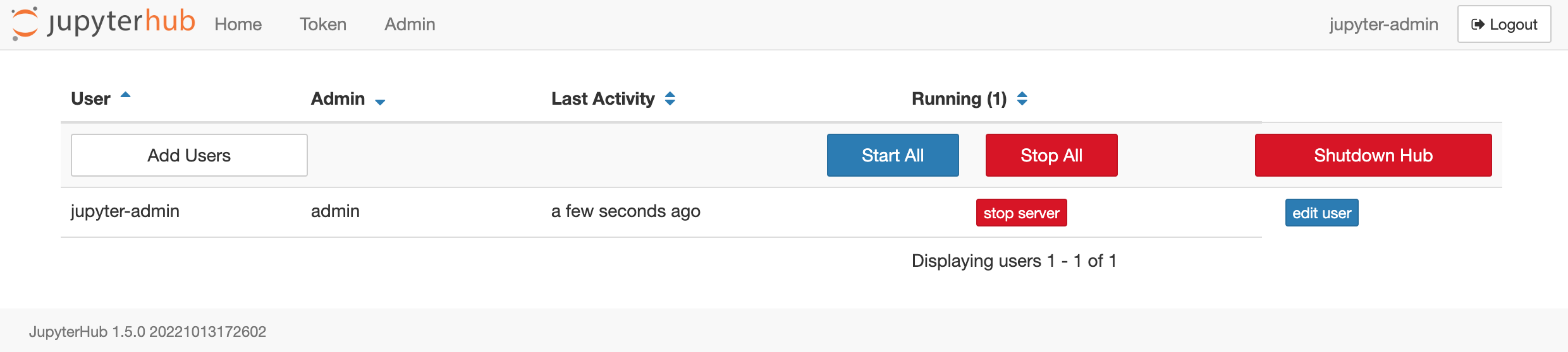
New users can be added using Add Users
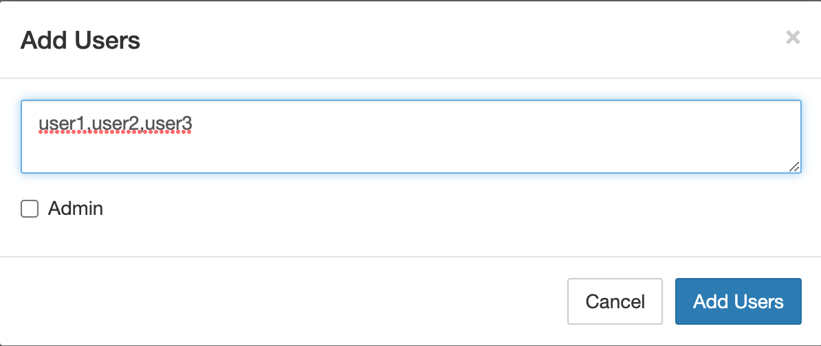
13.4.4.2. Default link from home directory to Lustre directory
$ sudo mkdir /fast/shared
$ sudo chown root:jupyterhub-users /fast/shared
$ sudo chmod 1777 /fast/shared
$ sudo chmod g+s /fast/shared
Next, change /etc/skel to set /fast/shared to be linked when creating a new user.
$ sudo ln -s /fast/shared /etc/skel/fast_shared
13.4.4.3. Using JupyterLab Interface
TLJH has a JupyterNotebook interface by default, but you can switch to JupyterLab, which has richer functionality, with the following command.
$ sudo tljh-config set user_environment.default_app jupyterlab
$ sudo tljh-config reload hub
For more advanced usage method, please refer to the official TLJH Docs. TLJH Installing on your own server
13.4.5. Installation method of JupyterHub in a distributed environment (JupyterHub + Kubernetes)
13.4.5.1. Preparation of cluster environment and Kubernetes environment
13.4.5.2. Installation of JupyterHub
Use Helm , the Kubernetes package management tool, to perform the installation. At the login node, execute the following.
$ helm repo add jupyterhub https://jupyterhub.github.io/helm-chart/
$ helm repo update
JupyterHub helm-chart has been installed. Prepare an empty config.yaml file and execute the following. If config.yaml is empty, it will work according to the Default value.
$ helm upgrade --cleanup-on-fail --install <helm-release-name> jupyterhub/jupyterhub --namespace <k8s-namespace> --create-namespace --version=<chart-version> --values config.yaml
For example, to execute version 2.0.0 with <helm-release-name>, <k8s-namespace> as jupyter, do the following.
$ helm upgrade --cleanup-on-fail --install jupyter jupyterhub/jupyterhub --namespace jupyter --create-namespace --version=2.0.0 --values config.yaml
JupyterHub has been deployed on Kubernetes.
$ kubectl get pods -n jupyter
13.4.5.3. JupyterHub for machine learning setting example
As an example, the following is performed.
Password management method settings
Data-Science Notebook image settings
Resource settings
Shared folder settings
After all settings are made, config.yaml will become like this
hub:
config:
JupyterHub:
authenticator_class: firstuseauthenticator.FirstUseAuthenticator
singleuser:
image:
name: jupyter/datascience-notebook
tag: latest
cpu:
limit: 32
guarantee: 16
profileList:
- display_name: "GPU Server"
description: "Spawns a notebook server with access to a GPU"
kubespawner_override:
extra_resource_limits:
nvidia.com/gpu: "1"
memory:
limit: 50G
guarantee: 50G
storage:
capacity: 100Gi
extraVolumes:
- name: shm-volume
emptyDir:
medium: Memory
extraVolumeMounts:
- name: shm-volume
mountPath: /dev/shm
Here is an explanation of the settings
hub:
config:
JupyterHub:
authenticator_class: firstuseauthenticator.FirstUseAuthenticator
singleuser:
image:
name: jupyter/datascience-notebook
tag: latest
singleuser:
cpu:
limit: 32
guarantee: 16
profileList:
- display_name: "GPU Server"
description: "Spawns a notebook server with access to a GPU"
kubespawner_override:
extra_resource_limits:
nvidia.com/gpu: "1"
memory:
limit: 50G
guarantee: 50G
storage:
capacity: 100Gi
extraVolumes:
- name: shm-volume
emptyDir:
medium: Memory
extraVolumeMounts:
- name: shm-volume
mountPath: /dev/shm
First, assuming that the Default StorageClass is set, create the following setting file (Assume shared-directory.yaml).
kind: PersistentVolumeClaim
apiVersion: v1
metadata:
name: jupyterhub-shared-volume
namespace: jupyter
spec:
accessModes:
- ReadWriteMany
volumeMode: Filesystem
resources:
requests:
storage: 10000Gi
Deploy PVCs using settings files.
$ kubectl create -f shared-directory.yaml
singleuser:
storage:
extraVolumes:
....
- name: jupyterhub-shared
persistentVolumeClaim:
claimName: jupyterhub-shared-volume
extraVolumeMounts:
....
- name: jupyterhub-shared
mountPath: /home/jovyan/shared
This will create a shared folder “shared” among users.
13.4.6. Reference URL
13.5. LustreClient update procedure
lustre-2.14.0_ddn198:Please use this version for Rocky 8.
lustre-2.14.0_ddn242:Please use this version for Ubuntu22.04, Ubuntu24.04 and Rocky 9.
Note
Depending on your environment, additional packages may be required, so please take action appropriately.
13.5.1. In case of Rocky 8 virtual machine
The procedure for updating from the installed version to the new provided version (lustre-2.14.0_ddn198) is described below.
- Suspend the Lustre service
# systemctl stop lustre_client # systemctl status lustre_client
- Uninstalling the old OFED driver
# /usr/sbin/ofed_uninstall.sh - Installing the new OFED driverFrom the Mellanox web, download the OFED driver ISO image “MLNX_OFED_LINUX-23.10-5.1.4.0-rhel8.10-x86_64.iso”.Mount the ISO image and run the installation script. At this time, specify “–guest (For VM guest OS)”.
# mount -o ro,loop MLNX_OFED_LINUX-23.10-5.1.4.0-rhel8.10-x86_64.iso /mnt
# cd /mnt
# ./mlnxofedinstall --guest
- Download package
# wget http://172.16.2.26/lustre-2.14.0_ddn198.tar.gz - Package deployment
# tar zxf lustre-2.14.0_ddn198.tar.gz # cd lustre-2.14.0_ddn198
- Building the LustreClient package
# dnf config-manager --set-enabled powertools # dnf install libmount-devel libyaml-devel json-c-devel # LANG=C # sh autogen.sh # ./configure --with-o2ib=/usr/src/ofa_kernel/default --disable-server --disable-lru-resize # make rpms
- Installing the LustreClient package
# rpm -Uvh kmod-lustre-client-2.14.0_ddn198-1.el8.x86_64.rpm lustre-client-2.14.0_ddn198-1.el8.x86_64.rpm - System restart
# rebootAfter restarted, confirm that high-speed storage area (/fast) and large-capacity area (/large) are mounted.
13.5.2. In case of Rocky 9 virtual machine
The procedure for updating from the installed version to the new provided version (lustre-2.14.0_ddn242) is described below.
- Suspend the Lustre service
# systemctl stop lustre_client # systemctl status lustre_client
- Uninstalling the old OFED driver
# /usr/sbin/ofed_uninstall.sh --force - Uninstalling the LustreClient package
# rpm -e kmod-lustre-client-2.14.0_ddn198 lustre-client-2.14.0_ddn198 - OS Update
# dnf update -y - System restart
# reboot - Installing the new OFED driverFrom the NVIDIA web, download and install the OFED driver RPM.
# wget https://www.mellanox.com/downloads/DOCA/DOCA_v3.3.0/host/doca-host-3.3.0-088000_26.01_rhel9.x86_64.rpm
# rpm -i doca-host-3.3.0-088000_26.01_rhel9.x86_64.rpm
# dnf clean all
# dnf -y install doca-ofed
- Download package
# wget http://172.16.2.26/lustre-2.14.0_ddn242.tar.gz
# wget http://172.16.2.26/lustre-2.14.0_ddn242.rocky.patch
- Package deployment
# tar zxf lustre-2.14.0_ddn242.tar.gz
# cd lustre-2.14.0_ddn242
# patch -p1 < ../lustre-2.14.0_ddn242.rocky.patch
- Building the LustreClient package
# dnf install libmount-devel kernel-abi-stablelists
# dnf --enablerepo=devel install libyaml-devel json-c-devel
# LANG=C
# sh autogen.sh
# ./configure --with-o2ib=/usr/src/ofa_kernel/x86_64/$(uname -r) --disable-server --disable-lru-resize
# make rpms
# make dkms-rpms
- Installing the LustreClient package
# dnf install lustre-client-2.14.0_ddn242-1.el9.x86_64.rpm lustre-client-dkms-2.14.0_ddn242-1.el9.noarch.rpm - System restart
# rebootAfter restarted, confirm that high-speed storage area (/fast) and large-capacity area (/large) are mounted.
13.5.3. In case of Ubuntu20.04 virtual machine
The procedure for updating from the installed version to the new provided version (lustre-2.12.9_ddn48) is described below.
- Suspend the Lustre service
$ sudo systemctl stop lustre_client
$ sudo systemctl status lustre_client
- Delete current LusterClient using the dkms command.
$ sudo dkms uninstall -m lustre-client-modules -v 2.12.9-ddn26 -k $(uname -r)
$ sudo dkms remove -m lustre-client-modules -v 2.12.9-ddn26 -k $(uname -r)
- Download packages and patches
$ wget http://172.16.2.26/lustre-2.12.9_ddn48.tar.gz
$ wget http://172.16.2.26/lustre-2.12.9_ddn48.ubuntu20.04.patch
- Deploying and patching packages
$ tar zxf lustre-2.12.9_ddn48.tar.gz $ cd lustre-2.12.9_ddn48 $ patch -p1 < ../lustre-2.12.9_ddn48.ubuntu20.04.patch - Building the LustreClient package
$ ./configure --with-linux=/usr/src/linux-headers-$(uname -r) --with-o2ib=/usr/src/ofa_kernel/default --disable-server --disable-lru-resize
$ make dkms-debs
- Installing the LustreClient package
$ cd debs $ sudo apt install ./lustre-client-modules-dkms_2.12.9-ddn48-1_amd64.deb $ sudo apt install ./lustre-client-utils_2.12.9-ddn48-1_amd64.deb - System restart
$ sudo reboot
After restarted, confirm that high-speed storage area (/fast) and large-capacity area (/large) are mounted.
13.5.4. In case of Ubuntu22.04, Ubuntu24.04 virtual machine
The procedure for updating from the installed version to the new provided version (2.14.0-ddn242) is described below.
- Suspend the Lustre service
$ sudo systemctl stop lustre_client
$ sudo systemctl status lustre_client
- Delete current LusterClient using the dkms command.
$ sudo dkms uninstall -m lustre-client-modules -v 2.14.0-ddn198 -k $(uname -r)
$ sudo dkms remove -m lustre-client-modules -v 2.14.0-ddn198 -k $(uname -r)
- Download packages and patches
$ wget http://172.16.2.26/lustre-2.14.0_ddn242.tar.gz
- Package deployment
$ tar zxf lustre-2.14.0_ddn242.tar.gz $ cd lustre-2.14.0_ddn242 - Building the LustreClient package
$ LANG=C
$ sh autogen.sh
$ ./configure --with-o2ib=/usr/src/ofa_kernel/default --disable-server --disable-lru-resize
$ make dkms-debs
- Installing the LustreClient package
$ cd debs $ sudo apt install ./lustre-client-modules-dkms_2.14.0-ddn242-1_amd64.deb ./lustre-client-utils_2.14.0-ddn242-1_amd64.deb - System restart
$ sudo reboot
After restarted, confirm that high-speed storage area (/fast) and large-capacity area (/large) are mounted.
13.6. Confirm the number of points remaining in the project on the virtual machine
Follow the Mount procedure to mount the large capacity storage on the virtual machine that will use this function.
Create the directory by executing the following after the directory is created, point information is periodically acquired.
# mkdir /large/mdx_status
After acquiring point information (Maximum 1 hour), you can confirm the number of remaining points by executing the following.
$ /large/mdx_status/show_point
Update:            2024-04-01 11:41:54 JST
Remaining Points:     32929.18
Expiration Date:   2024-09-30 JST

See https://oprpl.mdx.jp/ for more detail.
The meaning of each item are as follows.
Update: Date and time when the point information was acquired
Remaining Points: Number of points remaining
Expiration Date: The furthest expiration date among the points you own.
Please refer to Point usage status in the user portal if you would like to see individual point information.